
Liquid detergent throwing device

A technology for dispensing devices and detergents, which is applied to washing devices, other washing machines, textiles, and papermaking, etc. It can solve the problems of cumbersome operation, inaccurate dosing and measurement, and complex structure, and achieve low cost, simplified electrical circuits, and accurate dosing and measurement. Effect

Pending Publication Date: 2017-10-24
HANGZHOU KAMBAYASHI ELECTRONICS
View PDF12 Cites 11 Cited by
  • Summary
  • Abstract
  • Description
  • Claims
  • Application Information

AI Technical Summary

Problems solved by technology

[0008] The present invention solves the problems of inaccurate metering, complex structure, and cumbersome operation of the device for automatically injecting detergent in the washing machine in the prior art: for this purpose, a liquid detergent injecting device of the present invention is provided. The device is simple in structure and low in cost. Easy to use

Method used


Image

  • Liquid detergent throwing device
  • Liquid detergent throwing device
  • Liquid detergent throwing device

Examples


Embodiment 1

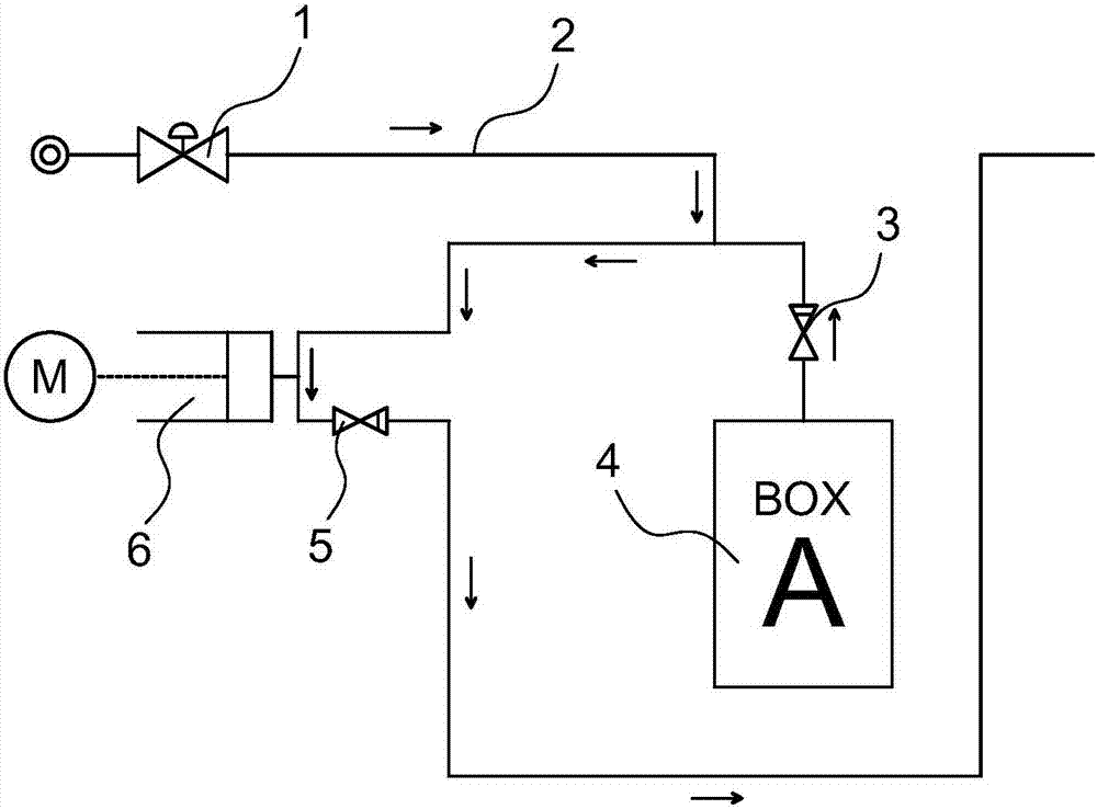
[0052] A liquid detergent delivery device, see figure 1 , the entrance of the main channel 2 is connected with a water inlet valve 1, the water inlet valve is preferably an electromagnetic water inlet valve, the outlet of the main channel 2 is connected to the water inlet of the washing bucket, and is provided with a piston 6, a valve A3, a valve B5 and a detergent A box 4, The piston 6 is connected to the main channel 1, the water inlet section of the main channel is formed between the piston inlet and the main channel inlet, the water outlet section of the main channel is formed between the piston outlet and the main channel outlet, the inlet of the valve A3 is connected with the detergent A box 4, and the valve The outlet of A3 bypasses the water inlet section of the main channel, the valve B5 is connected to the water outlet section of the main channel, and the inlet and outlet of the valve B5 correspond to the outlet of the piston 6 and the outlet of the main channel respe...

Embodiment 2

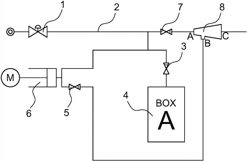
[0054] see figure 2 In this example, on the basis of Example 1, a Venturi negative pressure generator 8 is connected between the outlet of the main channel 2 and the water inlet of the detergent bucket. Connect the water inlet section of the main channel, the Venturi negative pressure generator 8 is connected to the water inlet of the washing bucket at port C as shown in the figure, and the negative pressure port of the Venturi negative pressure generator 8 is connected to the main channel 2 outlet at port B as shown in the figure .

Embodiment 3

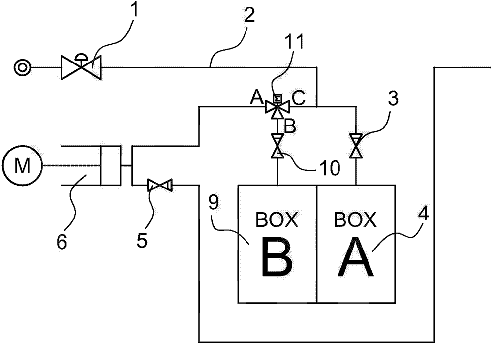
[0056] see image 3 , in this case at figure 1 Basically, a two-position three-way valve 11 is connected to the water inlet section of the main channel. The outlet of the valve A is described above, and the other inlet of the two-position three-way valve is connected to the detergent B box 9 after the B port in the figure is connected to the valve D.


PUM


Abstract

The invention provides a liquid detergent throwing device which is accurate in metering, simple in structure, low in cost and convenient to use and operate. The liquid detergent throwing device is provided with a main channel (2), a water inlet valve (1) is connected to a main channel inlet, a main channel outlet is connected with a washing bucket water inlet, the liquid detergent throwing device is provided with a piston (6), a one-way valve A (3), a one-way valve B (5) and a detergent A box (4), the piston is connected to the main channel, a main channel water inlet section is constituted between a piston inlet and the main channel inlet, a main channel outlet section is constituted between a piston outlet and the main channel outlet, an inlet of the one-way valve A is connected with the detergent box A, an outlet of the detergent box A bypasses the main channel water inlet section, the one-way valve B is connected to the main channel water outlet section, and an inlet and an outlet of the one-way valve B corresponds to the piston outlet and the main channel outlet respectively. The liquid detergent throwing device is used for feeding water for a washing machine and throwing detergent.

Description

technical field [0001] The invention relates to a device for injecting liquid preparations, in particular to a device for automatically injecting detergent for washing machines. Background technique [0002] With the acceleration of the pace of life and the continuous improvement of consumers' energy-saving awareness, users pay more attention to energy-saving and convenient home appliances when purchasing homes and appliances. As a household appliance with high frequency of household use, washing machine is energy-saving and convenient has become an important factor for customers to choose and buy. Washing machines with the function of automatically adding detergent are therefore more and more popular among users. However, most of the ordinary washing machines on the market currently add detergent manually when washing clothes, and it is difficult to control the dosage. The effect is poor and the cleaning ratio is low; when the amount of detergent is too large, it not only ...

Claims


Application Information

Patent Timeline
Patent Type & Authority Applications(China)
IPC IPC(8): D06F39/02
CPCD06F39/02D06F39/022
Inventor 鲍鹏飞劳维宣王华
Owner HANGZHOU KAMBAYASHI ELECTRONICS
Learn More