
A kind of ceiling and wall decoating device for building

A coating device and ceiling technology, which is applied in construction, building maintenance, building construction, etc., can solve the problems of dust greatly affecting air quality, not being safe enough, and not being able to meet the needs of use, so as to achieve easy and convenient removal process, prevent respiratory tract infection, Effortless work process

Active Publication Date: 2019-05-10
CHINA NUCLEAR IND ZHONGYUAN CONSTR
View PDF6 Cites 0 Cited by
  • Summary
  • Abstract
  • Description
  • Claims
  • Application Information

AI Technical Summary

Problems solved by technology

[0005] The purpose of the present invention is to provide a kind of building ceiling and wall coating device, to solve the existing building ceiling and wall coating work on the market that the above-mentioned background technology proposes. Lifting the head up for a long time will not only make the efficiency and effect of coating removal too low, but also the operator will work very hard during the removal process, which is not practical enough, and the removed coating will fall to the ground when this method is removed. It increases the difficulty of floor cleaning, and the coating particles will fall into the eyes of the operator, which is not safe enough. During the removal process, the ceiling and walls cannot be sprayed with water, resulting in low efficiency of ceiling decoating and great influence of dust. The problem of air quality, the existence of these problems has affected the process of de-coating the ceiling of the house, which cannot meet the needs of use

Method used


Image

  • A kind of ceiling and wall decoating device for building
  • A kind of ceiling and wall decoating device for building
  • A kind of ceiling and wall decoating device for building

Examples


Embodiment Construction

[0020] The following will clearly and completely describe the technical solutions in the embodiments of the present invention with reference to the accompanying drawings in the embodiments of the present invention. Obviously, the described embodiments are only some, not all, embodiments of the present invention. Based on the embodiments of the present invention, all other embodiments obtained by persons of ordinary skill in the art without making creative efforts belong to the protection scope of the present invention.

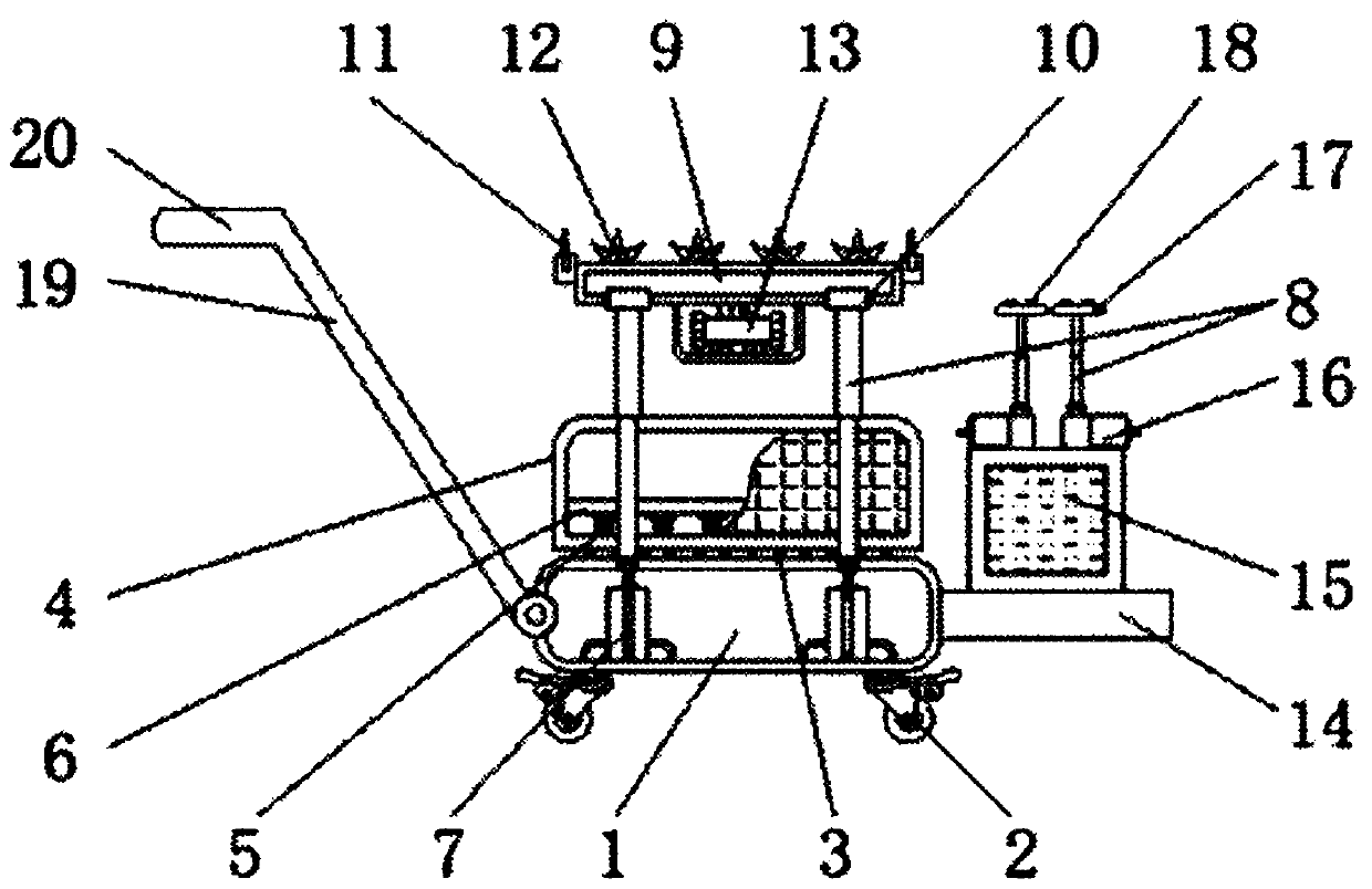
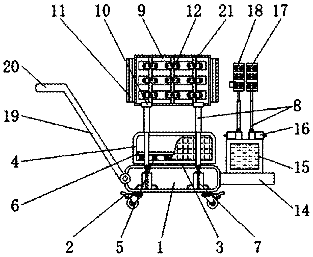
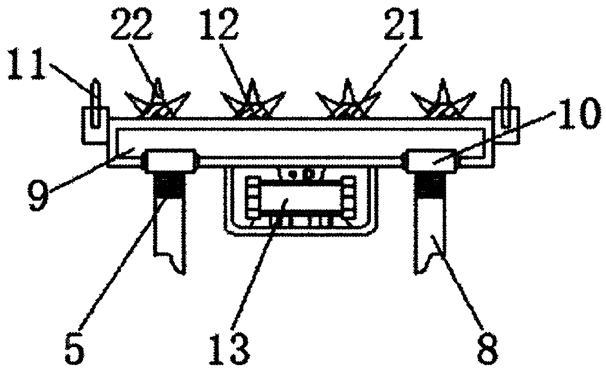
[0021] see Figure 1-5, the present invention provides a technical solution: a building ceiling and wall coating device, including a first base 1, a universal wheel 2, a roller 3, a dustbin 4, a shock absorbing spring 5, an inner plate 6, and a cylinder 7 , telescopic rod 8, fixed plate 9, rotating shaft 10, blade 11, crushing device 12, vibration motor 13, second base 14, water tank 15, water pump 16, adjustment surface 17, nozzle 18, push rod 19, push handle...


PUM


Abstract

The invention discloses an architectural coating removing device for ceilings and walls. The device comprises a first base, a fixed plate, a second base and adjusting surfaces. Universal wheels are arranged at the bottom end of the first base, damping springs are fixed to the bottom of a trash can, air cylinders are arranged in the first base, telescopic rods are connected to the upper portions of the air cylinders, blades are arranged at the left and right ends of the fixed plate, crushing devices are arranged on the surface of the fixed plate, a vibration motor is fixed to the bottom end of the fixed plate, telescopic rods are mounted on the lower portions of the adjusting surfaces, rolling shafts are arranged in the fixed plate, the crushing devices are connected to the surfaces of the rolling shafts in a sleeving mode, and crushing columns are fixedly mounted on the surfaces of the crushing devices. According to the fixed plate mounted on the architectural coating removing device for the ceilings and the walls, coating removing treatment for the ceilings and the walls from any angles can be satisfied through a rotary shaft, so that the demands of various angles are met by the architectural coating removing device for the ceilings and the walls, and the practicability is improved.

Description

technical field [0001] The invention relates to the technical field of construction machinery, in particular to a ceiling and wall coating removal device for construction. Background technique [0002] Architecture is a discipline that studies architecture and its environment. Architecture is a discipline that spans engineering technology and humanities. Architecture involves architectural art and architectural technology, as well as the aesthetic aspect of architectural art as a practical art. On the practical side, they are distinct but closely related, and their weight varies widely from case to case and from building to building. [0003] Architecture is a mirror of the times. It melts and reflects the aesthetic pursuit of an era and a nation with its unique artistic language. In the process of its development, architectural art constantly shows the material and spiritual civilization created by human beings. Image, with four-dimensional space and the fluidity of the ti...

Claims


Application Information

Patent Timeline
Patent Type & Authority Patents(China)
IPC IPC(8): E04G23/00
CPCE04G23/00E04G23/006
Inventor 时光张树林陆宽
Owner CHINA NUCLEAR IND ZHONGYUAN CONSTR
Learn More