Subway safety door

A safety door and subway technology, applied in the field of screen doors, can solve the problems of emergency door glass impact damage, emergency door sagging, etc., and achieve the effect of preventing accidental damage

Inactive Publication Date: 2017-10-24
BEIJING DINGHAN TECH GRP CO LTD
0 Cites 0 Cited by

AI-Extracted Technical Summary

Problems solved by technology

The hinged emergency door has a simple structure, is easy to produce, and is relatively easy to adjust. However, since the stress point is on the side box, one end of the emergency door will sag after a long period of use; while the emergency door in the ...

Method used

Further, described installation plate 3 is a Z-shaped installation strip, and this installation strip comprises the top shaft installation area 9 and the fixed area 10 of fixed installation strip in order to install the top shaft, in the fixed area 10 Several slotted holes 11 are provided, and the installation strip is adjustablely connected to the fixing plate 12 on the top of the side box 2 through the slotted holes 11 and bolts. The installation plate 3 of the present invention adopts the installation strip, and the installation strip can be connected to the fixed plate 12 on the top of the side box 2 by bolts due to its longer length, so the operating space is larger when connecting, and the bolt connection or When i...

Abstract

The invention discloses a subway safety door which comprises an emergency door and a side box, wherein the emergency door is connected with the side box. An installing plate is detachably connected with the top part of the side box, and a top shaft is detachably installed in the installing plate; a vertical frame is fixed to the side where the emergency door and the side box are connected, and an upper shaft base is fixedly connected with the top part of the vertical frame; a shaft hole is formed in the upper shaft base, and the top shaft is rotatably arranged in the upper shaft base through the shaft hole; and the bottom part of the vertical frame is rotatably arranged on the ground or ground sill through a rotating assembly. The emergency door of the subway safety door is not prone to drooping after long time using, and rapid maintaining and changing can be achieved.

Application Domain

Railway componentsWing arrangements +3

Technology Topic

EngineeringMullion +2

Image

  • Subway safety door
  • Subway safety door
  • Subway safety door

Examples

  • Experimental program(1)

Example Embodiment

[0019] Below in conjunction with accompanying drawing and embodiment the present invention will be further described:
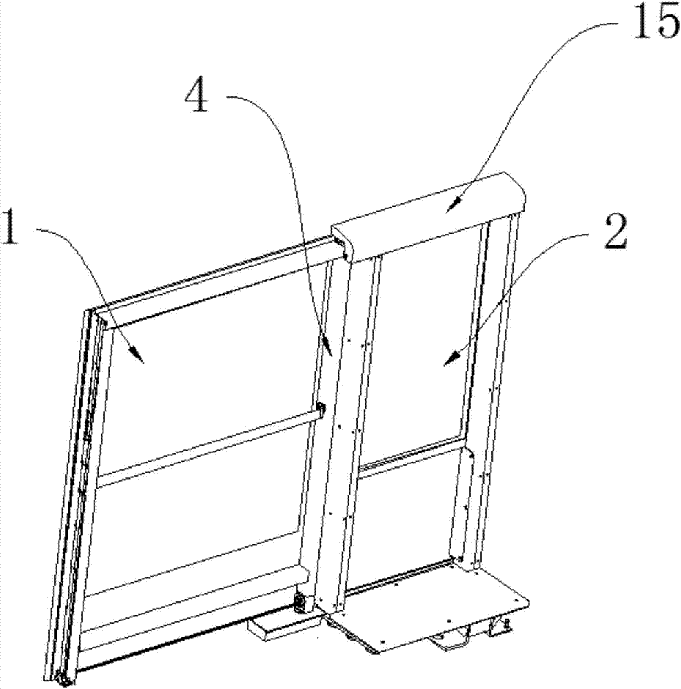
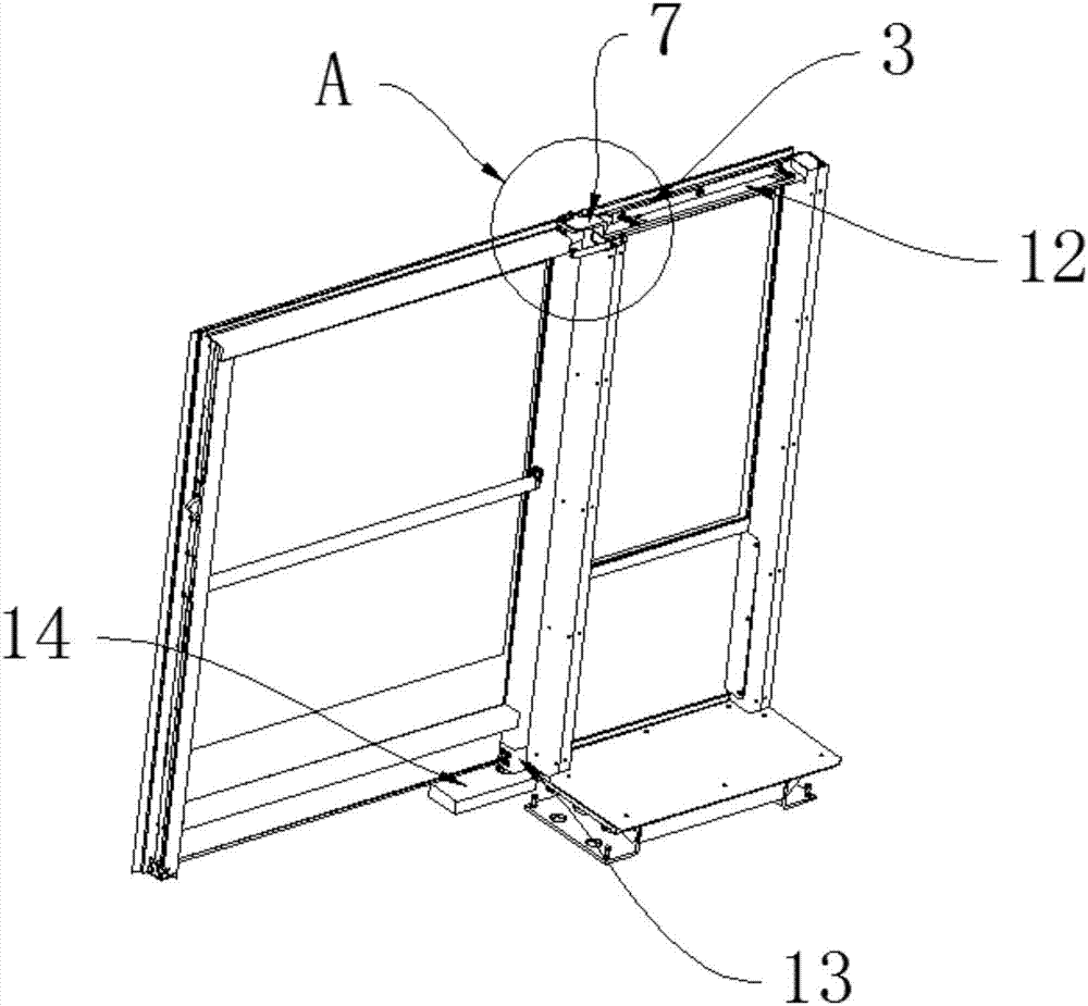
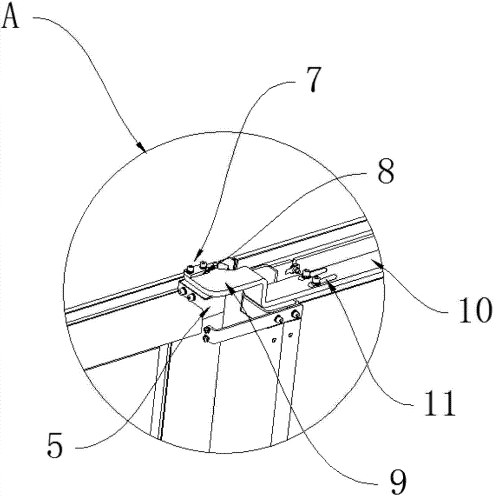
[0020] see Figure 1 to Figure 5 A subway safety door shown includes a connected emergency door 1 and a side box 2, the top of the side box 2 is detachably connected with a mounting plate 3, and a top shaft is detachably installed in the mounting plate 3, and the emergency A mullion 4 is fixed on the side where the door 1 and the side box 2 are connected, and an upper shaft seat 5 is fixedly connected to the top of the mullion 4, and an shaft hole 6 is opened in the upper shaft seat 5, and the top shaft passes through the shaft hole 6 is rotatably set in the upper shaft seat 5, and the bottom of the mullion 4 is rotatably set on the ground or sill by a rotating assembly.
[0021] When the present invention is in use, since the top of the emergency door 1 is rotatably connected with the upper shaft seat 5 installed by the mullion 4 and the mullion 4 on the side box 2, the bottom of the emergency door 1 is connected to the ground through a rotating assembly, so the emergency door 1 The load-bearing point of the side box 2 is transferred to the ground. Compared with the structure of the hinge, the side box 2 is prevented from being directly pulled and deformed, so the emergency door 1 is avoided from sagging. In addition, since the mounting plate 3 is detachably connected to the emergency door 1, and the jacking shaft is detachably connected to the mounting plate 3, when the emergency door 1 needs to be repaired and replaced, the jacking shaft is first disassembled, Then the safety plate 3 is disassembled, and finally the emergency door 1 can be taken out from the rotating assembly on the ground, and the replacement of the emergency door 1 is completed quickly, which solves the problem that the maintenance and replacement of the emergency door 1 takes too long.
[0022] Further, the top shaft is a flange shaft 7, and the flange shaft 7 is screwed to the mullion 4 through the flange plate 8 thereon. Since the flange shaft 7 has a flange plate 8, corresponding threaded holes can be set on the flange plate 8 and the mounting plate 3 to realize quick disassembly and installation of the top shaft.
[0023] Further, the installation plate 3 is a Z-shaped installation strip, which includes a top shaft installation area 9 for installing the top shaft and a fixed area 10 for fixing the installation strip. In the fixed area 10, several Slotted hole 11, the mounting bar is adjustable on the fixed plate 12 at the top of the side box 2 through the slotted hole 11 and bolts. The installation plate 3 of the present invention adopts the installation strip, and the installation strip can be connected to the fixed plate 12 on the top of the side box 2 by bolts due to its longer length, so the operating space is larger when connecting, and the bolt connection or When it is disassembled, the field of vision is wider and will not be interfered. At the same time, since the installation strip is connected to the fixed plate 12 through the long slot hole 11, the length can be adjusted during installation and maintenance, so that the emergency door 1 remains There will be no offset in the vertical state, making it more aesthetically pleasing.
[0024] Further, the rotating assembly includes a lower axle seat 13 fixedly arranged at the bottom of the mullion, and a ground spring 14 fixedly arranged on the ground or on the sill, and the lower axle seat 13 includes a fixed block 16 and a lower wall rod 17, And be connected with ground spring 14 by the groove of lower wall rod 17 bottoms. The rotating assembly of the present invention is composed of the lower shaft seat 13 on the mullion 4 and the ground spring 14 on the ground or the sill. Through the rotating assembly, the control of the opening angle of the emergency door 1 can be realized, so that it can be positioned and avoid Due to the improper angle of the emergency door 1, the emergency door 1 is bumped and the glass is damaged. Specifically, the lower shaft seat 13 is welded by the fixing block and the lower wall rod 17 of the floor spring 14 (provided by the floor spring 14 manufacturer). When fixing the ground spring 14 in advance, the groove at the bottom of the lower wall bar 17 of the lower axle seat 13 is matched on the protrusion of the ground spring 14 to get final product.
[0025] Further, the top of the side box 2 is screwed with a cover plate 15 covering the installation strip. In order to effectively protect the installation slats from being deformed due to accidental impact, the top of the side box 2 is also screwed with a cover plate covering the installation slats, which can play a protective and dustproof role.
[0026] The preferred specific embodiments of the present invention have been described in detail above. It should be understood that those skilled in the art can make many modifications and changes according to the concept of the present invention without creative effort. Therefore, all technical solutions that can be obtained by those skilled in the art based on the concept of the present invention through logical analysis, reasoning or limited experiments on the basis of the prior art shall be within the scope of protection defined by the claims.

PUM

no PUM

Description & Claims & Application Information

We can also present the details of the Description, Claims and Application information to help users get a comprehensive understanding of the technical details of the patent, such as background art, summary of invention, brief description of drawings, description of embodiments, and other original content. On the other hand, users can also determine the specific scope of protection of the technology through the list of claims; as well as understand the changes in the life cycle of the technology with the presentation of the patent timeline. Login to view more.

Similar technology patents

A method for charging a lithium iron phosphate standby battery pack for suppressing circulating current generation

InactiveCN109167111Aavoid accidental damageExtended service life
Owner:ELECTRIC POWER RES INST STATE GRID SHANXI ELECTRIC POWER

Conveying rack for aluminum alloy profiles

InactiveCN102700778ASimple structureavoid accidental damage
Owner:ANHUI TONGXI JINPENG ALUMINUM

Equipment structure for taking and placing large-scale semiconductor printing plate

PendingCN112499262AIncrease productivityavoid accidental damage
Owner:技感半导体设备(南通)有限公司

Detachable slat angle adjustment mechanism

InactiveUS20180363709A1avoid accidental damage
Owner:SHEEN WORLD TECH CORP

Environment-friendly efficient purification faucet

InactiveCN108488475AEasy and quick installationavoid accidental damage
Owner:傅华中

Classification and recommendation of technical efficacy words

  • avoid accidental damage

Detachable slat angle adjustment mechanism

InactiveUS20180363709A1avoid accidental damage
Owner:SHEEN WORLD TECH CORP

A method for charging a lithium iron phosphate standby battery pack for suppressing circulating current generation

InactiveCN109167111Aavoid accidental damageExtended service life
Owner:ELECTRIC POWER RES INST STATE GRID SHANXI ELECTRIC POWER

Conveying rack for aluminum alloy profiles

InactiveCN102700778ASimple structureavoid accidental damage
Owner:ANHUI TONGXI JINPENG ALUMINUM

Environment-friendly efficient purification faucet

InactiveCN108488475AEasy and quick installationavoid accidental damage
Owner:傅华中

Equipment structure for taking and placing large-scale semiconductor printing plate

PendingCN112499262AIncrease productivityavoid accidental damage
Owner:技感半导体设备(南通)有限公司
Why Eureka
Try Eureka