Throttle valve structure and self-cleaning method for throttle valve carbon deposit

A throttle and self-cleaning technology, which is applied to engine components, engine control, machine/engine, etc., can solve the problems of the engine not working normally, and achieve the effect of solving the carbon deposit of the throttle

Pending Publication Date: 2017-10-24
BEIJING AUTOMOBILE RES GENERAL INST
View PDF6 Cites 6 Cited by
  • Summary
  • Abstract
  • Description
  • Claims
  • Application Information

AI Technical Summary

Problems solved by technology

[0004] In order to solve the above technical problems, the present invention provides a throttle structure and a self-cleaning method for carbon deposits in the throttle, which solves the problem that the engine cannot work normally due to carbon deposits in the throttle during the use of the vehicle

Method used


Image

  • Throttle valve structure and self-cleaning method for throttle valve carbon deposit
  • Throttle valve structure and self-cleaning method for throttle valve carbon deposit
  • Throttle valve structure and self-cleaning method for throttle valve carbon deposit

Examples


Embodiment 1

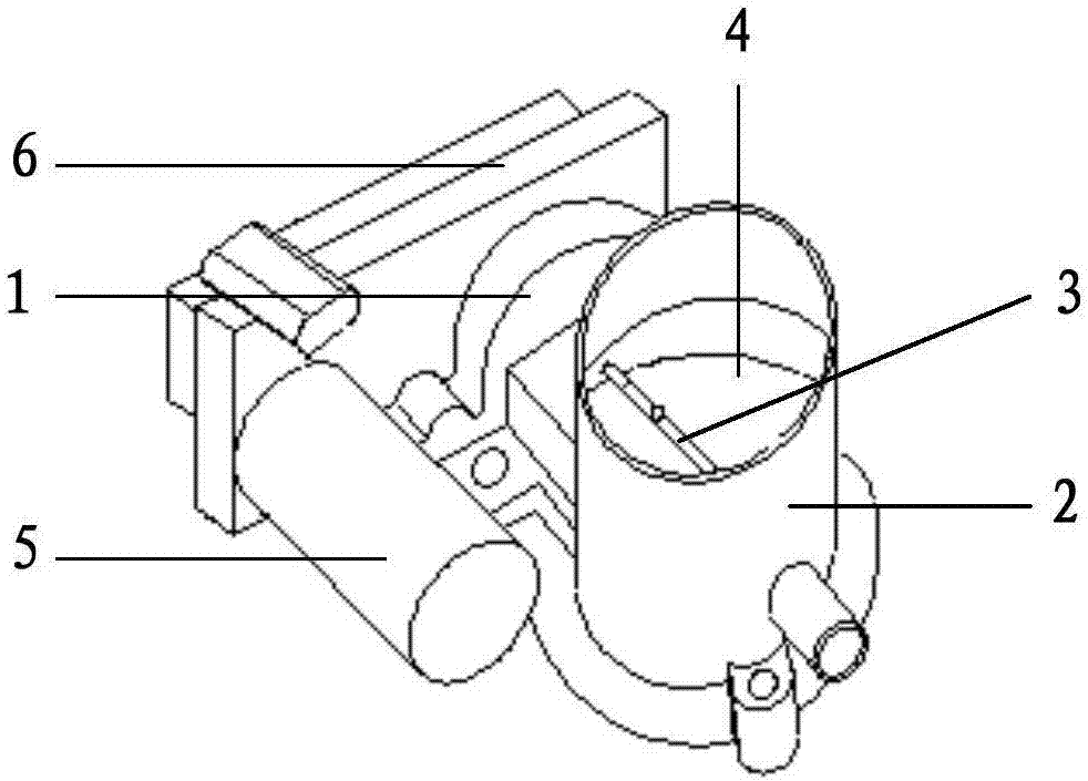
[0050] Such as figure 1 As shown, the embodiment of the present invention provides a throttle valve structure, including:

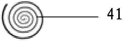
[0051] Valve body 1; intake pipe 2 installed on the valve body 1; butterfly valve shaft 3 vertically arranged inside the intake pipe 2; butterfly valve 4 installed on the butterfly valve shaft 3; integrated inside the butterfly valve 4 The heating wire 41; the power regulator connected with the heating wire 41; and the engine control unit ECU connected with the power regulator and the butterfly valve shaft 3;

[0052] Wherein, the ECU obtains the preset system value of the throttle valve by controlling the rotation of the butterfly valve shaft 3 and driving the butterfly valve 4; obtains the degree of carbon deposit in the throttle valve according to the system value; The degree of controlling the power regulator selects the heating mode of the heating wire 41, and controls the heating of the heating wire 41 according to the heating mode of the heating w...

Embodiment 2

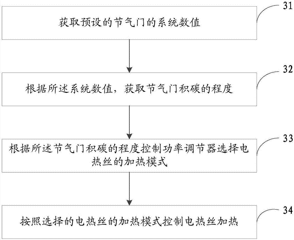
[0065] Such as image 3 Shown, the embodiment of the present invention also provides a kind of self-cleaning method of throttle valve carbon deposition, comprising:

[0066] Step 31, obtaining the preset system value of the throttle;

[0067] Step 32, according to the system value, obtain the degree of carbon deposit in the throttle valve;

[0068] Step 33. Control the power regulator to select the heating mode of the heating wire according to the degree of carbon deposit in the throttle valve;

[0069] Step 34: Control the heating of the heating wire according to the heating mode of the heating wire selected.

[0070] In this embodiment, before the ECU controls the carbon deposit self-cleaning of the throttle valve, it is necessary to first judge whether the vehicle system meets the self-cleaning condition, that is, whether there is a fault related to the throttle body in the vehicle engine control system, and if the self-cleaning condition is not satisfied, then Exit self...


PUM


Abstract

The invention discloses a throttle valve structure and a self-cleaning method for throttle valve carbon deposit. The throttle valve structure comprises a valve body, an air inlet pipe arranged on the valve body, a butterfly valve shaft vertically arranged in the air inlet pipe, a butterfly valve arranged on the butterfly valve shaft, an electric heating wire integrated in the butterfly valve, a power adjuster connected with the electric heating wire, and an ECU connected with the power adjuster and the butterfly valve shaft. When an engine shuts down, a system actively recognizes the carbon deposit situation, a proper self-cleaning mode is selected, the throttle valve body butterfly valve heating work manner is adopted, and two-level control is conducted on heating power; and through heating and evaporating of the carbon deposit on the butterfly valve, self-cleaning of a throttle valve body is achieved, and the problem of carbon deposit of a throttle valve can be effectively solved; and meanwhile a reference is provided for the ECU control strategy and throttle valve body design and development.

Description

technical field [0001] The invention relates to the field of engine throttles, in particular to a throttle structure and a self-cleaning method for carbon deposits in the throttle. Background technique [0002] With the increase of car ownership, there is congestion in most cities. When the car is running in low-to-medium load urban conditions for a long time, the oil gas containing water vapor enters the intake manifold through the part-load breathing tube. The oil and gas meet the cold air entering from the throttle body, and the oil and gas condense to form a jelly that adheres to the butterfly valve of the throttle body. As the accumulation of jelly increases, carbon deposits will eventually form near the butterfly valve, which will directly lead to adverse consequences such as difficulty in cold start of the engine, unstable idling operation, power drop, increased exhaust emissions, and increased fuel consumption. [0003] Throttle valve carbon deposit is a common faul...

Claims


Application Information

Patent Timeline
Patent Type & Authority Applications(China)
IPC IPC(8): F02D9/10F02B77/04F02B77/08
CPCF02B77/04F02B77/082F02B77/083F02D9/10
Inventor 赵志国徐蒙邵军陈英俊
Owner BEIJING AUTOMOBILE RES GENERAL INST
Why Eureka
Try Eureka