Cog belt and belt reduction device including same
A technology of deceleration device and toothed belt, which is applied in the direction of hoisting device, transmission device, transportation and packaging, etc., can solve the problems of inability to turn, increase noise, difficult layout, etc., and achieve the improvement of steering feeling, noise and vibration reduction. Effect
Inactive Publication Date: 2017-10-24
BANDO CHEM IND LTD
View PDF8 Cites 4 Cited by
- Summary
- Abstract
- Description
- Claims
- Application Information
AI Technical Summary
Problems solved by technology
Although this undesirable phenomenon can be eliminated to some extent by reducing the size of the teeth, on the other hand, the following new undesirable phenomenon may occur, that is, the strength of the teeth is reduced due to the reduction in the size of the teeth
If the strength of the teeth is reduced, when a large force is applied to the teeth, the teeth may be cut off, and the broken teeth may enter the pulley groove, causing the reduction mechanism to be locked, and then the steering cannot be turned.
For this reason, if the size of the belt teeth is reduced for the purpose of reducing the operating noise, the bandwidth has to be increased to ensure the strength of the teeth, resulting in an increase in the size of the reduction gear, and it becomes difficult to arrange the reduction gear in the vehicle body.
There is also the undesirable phenomenon that if the bandwidth is increased, the noise will increase
Method used
View moreImage
Smart ImageViewing Examples
Examples
Embodiment
[0089] Next, the results of the noise test performed on the toothed belt will be described.
Login to View More PUM
| Property | Measurement | Unit |
|---|---|---|
| distance | aaaaa | aaaaa |
| diameter | aaaaa | aaaaa |
| diameter | aaaaa | aaaaa |
Abstract
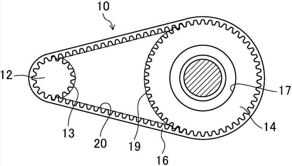
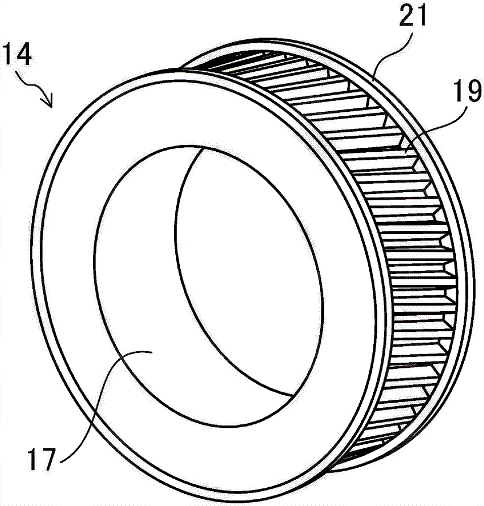
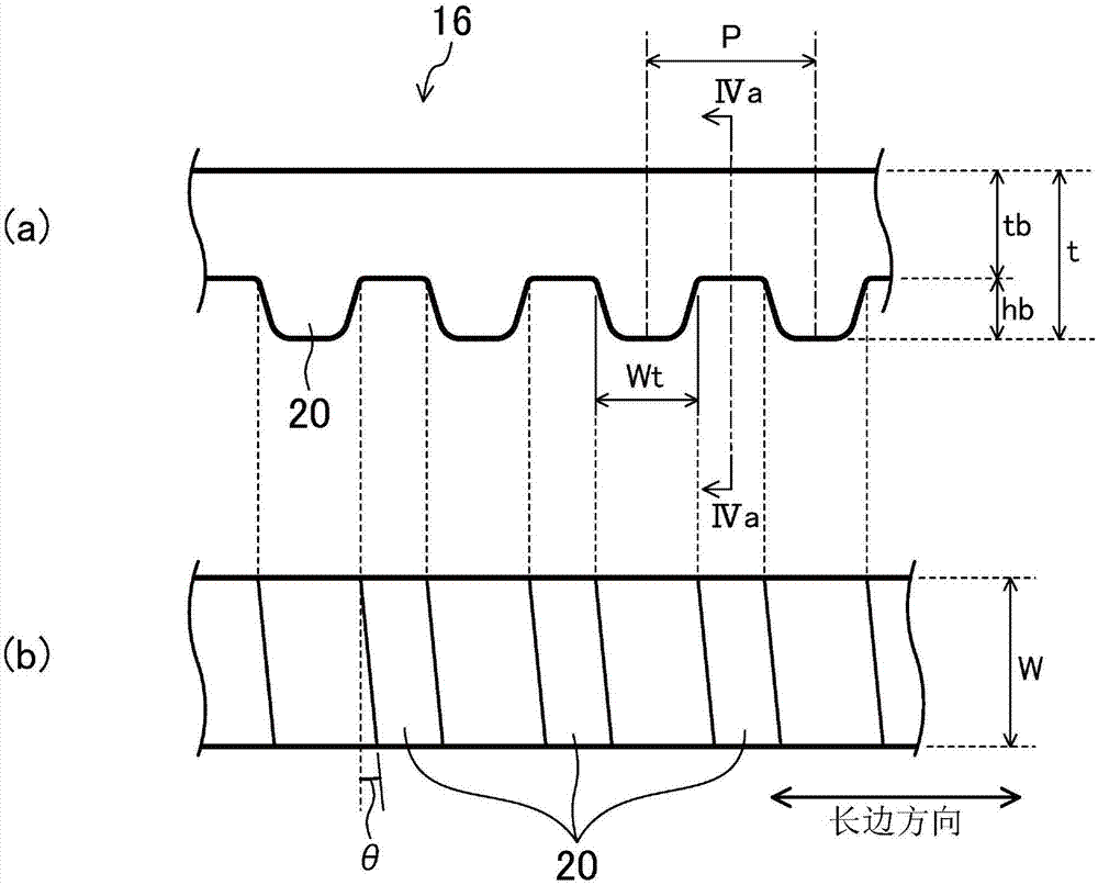
The invention relates to a cog belt and a belt reduction device including the cog belt. The cog belt includes a back portion and helical teeth on an inner peripheral side of the back portion, and a plurality of the helical teeth are arranged at a fixed pitch onn a belt length direction. The angle ([theta]) between the direction in which a tooth line of the helical tooth (20) extends and the direction of the belt width is higher than 7 degrees and lower than 10 degrees. When thickness of the back portion is represented by tb, the tooth height of the helical tooth (20) is represented by hb, and when the ratio A of tb to hb is calculated by A = 100 x tb / hb, A is 120% or more and 240% or less.
Description
[0001] This application is a divisional application with the application number 201380041744.1 submitted on July 5, 2013, and the title of the invention is "toothed belt and belt speed reduction device including the toothed belt". technical field [0002] The technology disclosed in this specification relates to a toothed belt for a power steering device. Background technique [0003] The technique of using a reduction gear having a belt in an electric power steering system for a vehicle is known. For example, Patent Document 1 discloses a belt speed reduction device using a friction belt, that is, a so-called V-belt. In this belt speed reducer, since power is transmitted by friction, it is necessary to apply a large tension to the belt to obtain a sufficient frictional force. For this reason, when the belt speed reducer described in Patent Document 1 is used, the torque at the time of no load increases, and the return of the steering wheel tends to be delayed. [0004] On...
Claims
Login to View More Application Information
Patent Timeline
 Patent Type & Authority Applications(China)
IPC IPC(8): F16G1/28F16H55/14B62D3/02
CPCB62D3/02F16G1/10F16G1/28F16H7/023F16H55/14B62D5/0424B62D5/04
Inventor 关口勇次中岛荣二郎
Owner BANDO CHEM IND LTD
Features
- R&D
- Intellectual Property
- Life Sciences
- Materials
- Tech Scout
- Unparalleled Data Quality
- Higher Quality Content
- 60% Fewer Hallucinations
Learn More Browse by: Latest US Patents, China's latest patents, Technical Efficacy Thesaurus, Application Domain, Technology Topic, Popular Technical Reports.
© 2025 PatSnap. All rights reserved.Legal|Privacy policy|Modern Slavery Act Transparency Statement|Sitemap|About US| Contact US: help@patsnap.com


