Transformer substation self-operation bird repelling device
A substation and self-operating technology, applied in the direction of switchgear, electrical components, animal repellent, etc., can solve the problems of large damage to birds, unsuitable for large-scale promotion, etc., and achieve powerful effects
- Summary
- Abstract
- Description
- Claims
- Application Information
AI Technical Summary
Problems solved by technology
Method used
Image
Examples
Embodiment 1
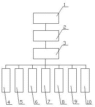
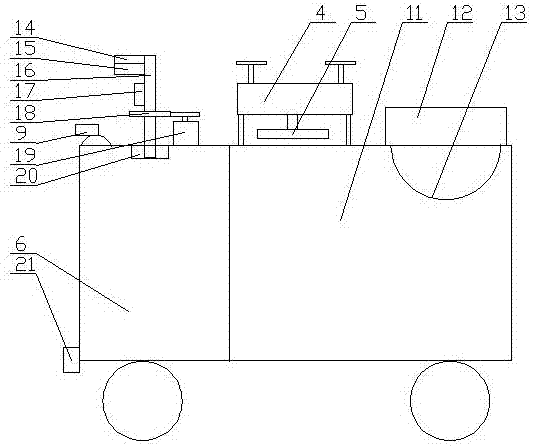
[0036] Embodiment one, such as figure 1 and figure 2 As shown, the present invention provides a substation self-running bird repelling device, including a mobile car 6 and a track line drawn in the substation, and the mobile car 6 is provided with a radar detection module 7, an ultrasonic bird repellent module 8 and a first camera 9 , the bottom of the mobile trolley 6 is provided with an identification mechanism 10 corresponding to the track line, a compartment 11 is provided behind the mobile trolley 6, a drone 4 is arranged on the compartment 11, and a bird's nest is arranged below the drone 4 The cleaning mechanism 5 for processing, the compartment 11 is provided with a housing mechanism for collecting bird's nests, the radar detection module 7, the ultrasonic bird repelling module 8, the identification mechanism 10, the first camera 9, the unmanned aerial vehicle 4, the cleaning mechanism 5 and the mobile trolley 6 are connected with the control module 3, and the contro...
Embodiment 2
[0042] Such as figure 1 and figure 2 As shown, the difference between this embodiment and Embodiment 1 is:
[0043] The radar detection module 7 and the ultrasonic bird repelling module 8 are arranged on the mobile car 6 through a rotating mechanism, and the rotating mechanism includes a rotating base 20 arranged on the moving car 6, and the rotating base 20 is provided with Rotating rod 16, the top of the rotating rod 16 is provided with the radar detection module 7, the middle part of the rotating rod 16 is provided with the ultrasonic bird repelling module 8, and the bottom of the rotating rod 16 is connected with the transmission gear 18 and is arranged on the The driving motor 19 on the mobile trolley 6 is connected, and the driving motor 19 is connected with the control module 3 .
[0044] The radar detection module 7 includes a radio wave transmitter 14 and a radio wave receiver 15 arranged on the top of the rotating rod 16 , and the radio wave transmitter 14 and rad...
Embodiment 3
[0052] Such as Figure 3 to Figure 5As shown, the difference between this embodiment and Embodiment 1 is:
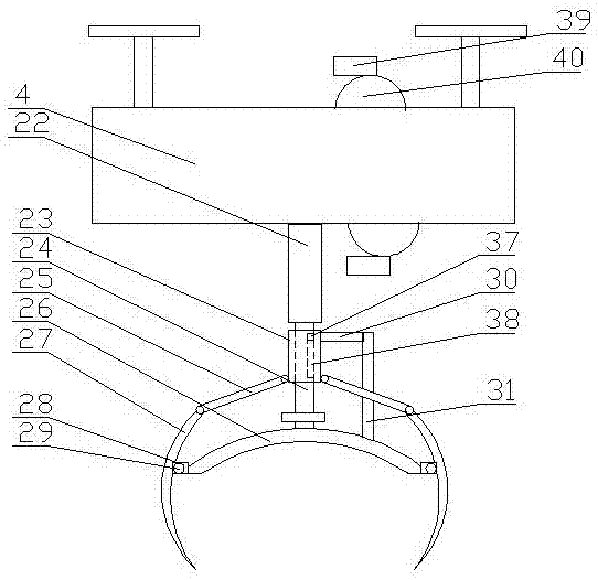
[0053] The cleaning mechanism 5 includes a first telescopic mechanism 22 arranged below the drone 4, an extension rod 24 is arranged at the lower end of the first telescopic mechanism 22, and an arc-shaped cover 26 with an opening downward is arranged at the lower end of the extension rod 24 A plurality of rotating brackets 28 are evenly distributed on the edge of the arc-shaped cover body 26, a rotating shaft 29 is arranged on the rotating bracket 28, a fixed claw 27 is movable on the rotating shaft 29, and a sliding sleeve is sleeved on the outside of the extension rod 24 23. The sliding sleeve 23 is provided with a sliding block 37, the extension rod 24 is provided with a chute 38 corresponding to the sliding block 37, and the lower end of the sliding sleeve 23 is rotated to set several crank arms that match the fixed pawl 27 25. The other end of the crank arm 25 is ...
PUM
 Abstract
Description
Claims
Application Information
 - R&D
- Intellectual Property
- Life Sciences
- Materials
- Tech Scout
- Unparalleled Data Quality
- Higher Quality Content
- 60% Fewer Hallucinations
Browse by: Latest US Patents, China's latest patents, Technical Efficacy Thesaurus, Application Domain, Technology Topic, Popular Technical Reports.
© 2025 PatSnap. All rights reserved.Legal|Privacy policy|Modern Slavery Act Transparency Statement|Sitemap|About US| Contact US: help@patsnap.com


