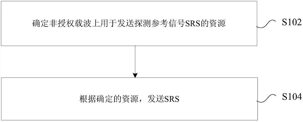
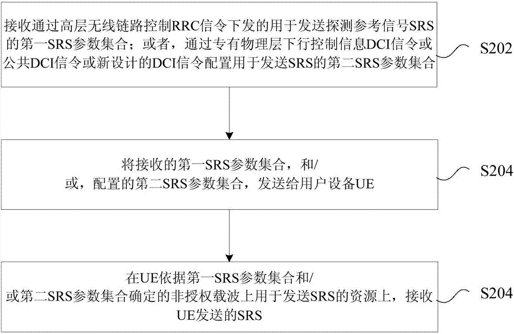
Sounding reference signal transmitting method and device, sounding reference signal receiving method and device, UE and base station
A technology of sounding reference signal and transmission method, which is applied in the field of receiving method, device, sounding reference signal transmission, UE and base station, and can solve the problem of few SRS transmission opportunities
- Summary
- Abstract
- Description
- Claims
- Application Information
AI Technical Summary
Problems solved by technology
Method used
Image
Examples
Embodiment 1
[0165] In this embodiment, a transmission method of a periodic sounding reference signal SRS on an unlicensed carrier is provided. It is assumed that the SRS parameter or parameter set is the same as that in the existing LTE protocol. The SRS parameter set includes at least one of the following: cell-level bandwidth C SRS , cell subframe configuration I SRS , UE-level bandwidth B SRS , frequency hopping bandwidth b hop , frequency domain position n RRC , duration, UE level I SRS Logo (corresponding to cycle T SRS and the subframe offset T within the period offset ), transmission comb cyclic shift Transmission comb number K TC , the number of antenna ports N ap .
[0166] For LAA, under frame structure 3 (the default is downlink subframe in a wireless frame, and uplink transmission can only be performed after the terminal receives the corresponding instruction or signaling), due to the difference in uplink and / or downlink traffic, As a result of LBT, the position ...
Embodiment 2
[0187] In this embodiment, a transmission method of an aperiodic sounding reference signal SRS on an unlicensed carrier is provided.
[0188] It is assumed that the SRS parameter or parameter set is the same as that in the existing LTE protocol. The SRS parameter set includes at least one of the following: cell-level bandwidth C SRS , cell subframe configuration I SRS , UE-level bandwidth B SRS , frequency hopping bandwidth b hop , frequency domain position n RRC , duration, UE level I SRS Logo (corresponding to cycle T SRS and the subframe offset T within the period offset ), transmission comb cyclic shift Transmission comb number K TC , the number of antenna ports N ap .
[0189] The difference between Embodiment 2 and Embodiment 1 is that the terminal can perform SRS transmission according to the four situations in Embodiment 1 above only after receiving the aperiodic SRS trigger signaling sent by the base station. Wherein, triggering the aperiodic SRS transmi...
Embodiment 3
[0207] In this embodiment, a method for determining the time-domain transmission position of the Sounding Reference Signal SRS is provided.
[0208] Based on Embodiments 1 and 2, according to the SRS parameter configuration in the existing protocol, the SRS transmission opportunity is limited to a certain extent in the LAA. Therefore, in this embodiment, a new SRS parameter set is designed for LAA. Specifically, how to determine the location of the SRS transmission on the unlicensed carrier.
[0209] The time-domain transmission location of the sounding reference signal SRS can be determined by one of the following methods:
[0210] Way 1: The period in the SRS parameter set and the subframe offset within the period are determined.
[0211] The elements in the SRS parameter set include at least one of the following: cell-level bandwidth, cell subframe configuration, UE-level bandwidth, frequency hopping bandwidth, frequency domain position, UE-level subframe configuration (c...
PUM
 Abstract
Description
Claims
Application Information
 - R&D
- Intellectual Property
- Life Sciences
- Materials
- Tech Scout
- Unparalleled Data Quality
- Higher Quality Content
- 60% Fewer Hallucinations
Browse by: Latest US Patents, China's latest patents, Technical Efficacy Thesaurus, Application Domain, Technology Topic, Popular Technical Reports.
© 2025 PatSnap. All rights reserved.Legal|Privacy policy|Modern Slavery Act Transparency Statement|Sitemap|About US| Contact US: help@patsnap.com


