Forming cylinder powder discharging device used for additive manufacturing equipment

An additive manufacturing and forming cylinder technology, applied in the field of additive manufacturing, can solve the problem of time-consuming and laborious cleaning of powder, and achieve the effect of reducing workload, pollution and powder quantity

Pending Publication Date: 2017-10-27
XIAN BRIGHT ADDTIVE TECH CO LTD
View PDF5 Cites 2 Cited by
  • Summary
  • Abstract
  • Description
  • Claims
  • Application Information

AI Technical Summary

Problems solved by technology

[0005] The purpose of the present invention is to provide a forming cylinder powder release device for additive manufacturing equipment, which solves the time-consuming and labor-intensive problem of cleaning powder after parts are formed

Method used


Image

  • Forming cylinder powder discharging device used for additive manufacturing equipment
  • Forming cylinder powder discharging device used for additive manufacturing equipment
  • Forming cylinder powder discharging device used for additive manufacturing equipment

Examples


Embodiment Construction

[0020] The present invention will be described in detail below in conjunction with the accompanying drawings and specific embodiments.

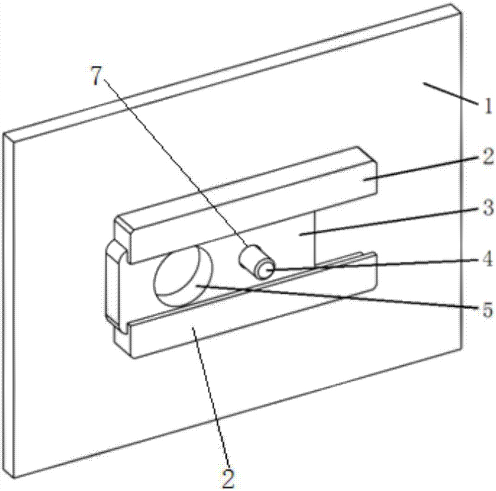
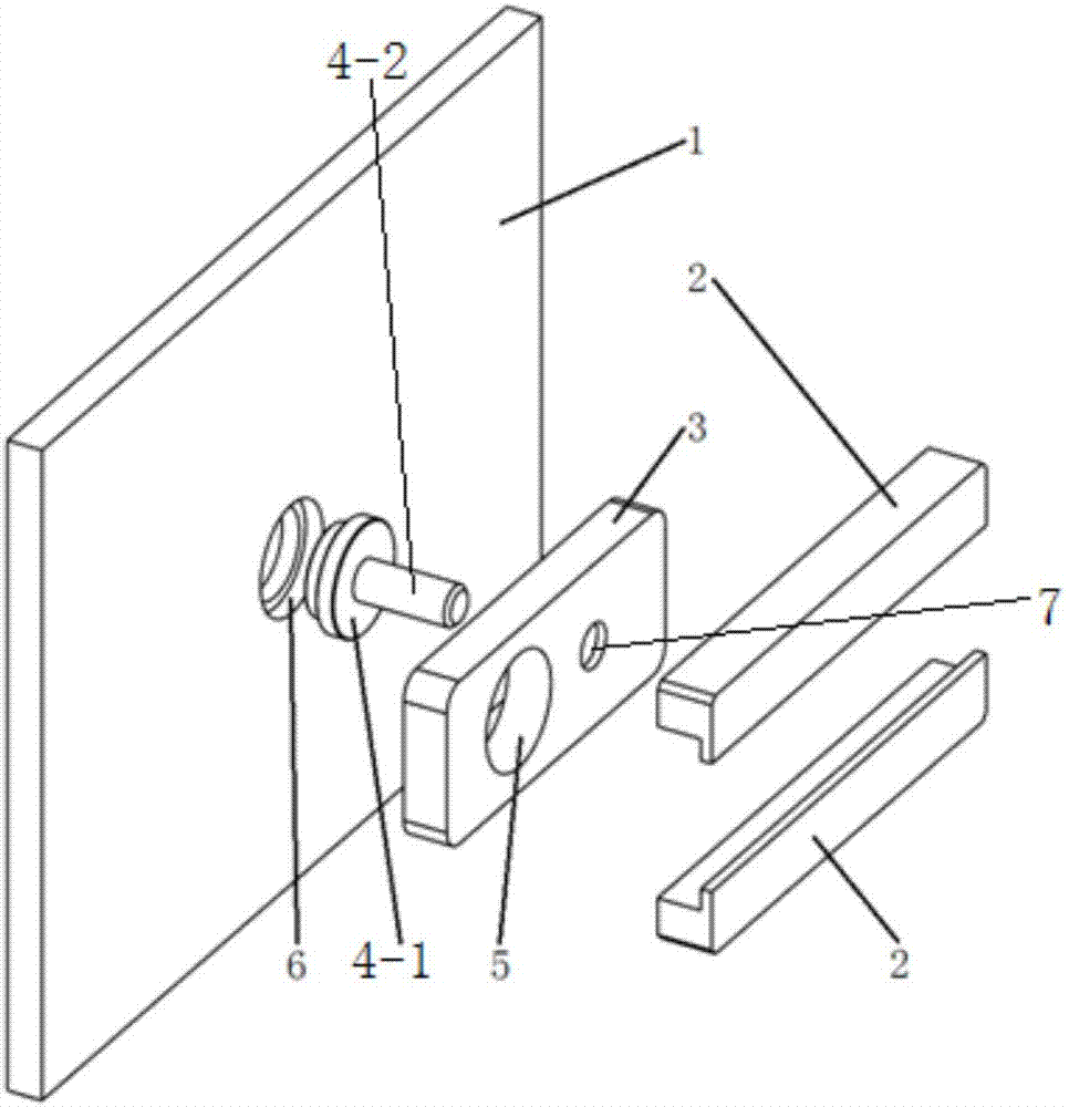
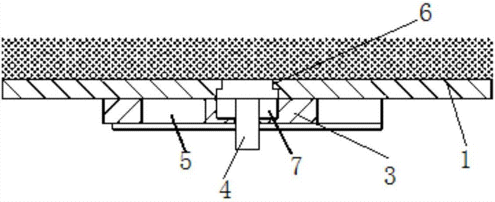
[0021] The present invention is a molding cylinder powder release device for additive manufacturing equipment, such as figure 1 , 2 As shown, the molding cylinder side plate 1 is included, and two slide rails 2 parallel to each other are arranged on one side of the molding cylinder side plate 1, and a vertical powder discharge movable plate 3 is embedded between the two slide rails 2. , the powder discharge movable plate 3 is respectively provided with a powder discharge opening A5 and a stepped hole 7, the center of the powder discharge hole opening A5 and the center of the stepped hole 7 are located on the same horizontal line, and the forming cylinder side plate 1 corresponding to the position of the stepped hole 7 A powder discharge opening B6 is provided, and the plug 4 passes through the stepped hole 7 and is stuck in the powder discha...


PUM


Abstract

The invention discloses a forming cylinder powder discharging device used for additive manufacturing equipment. The forming cylinder powder discharging device comprises a forming cylinder side plate, two mutually parallel sliding rails are arranged on one side face of the forming cylinder side plate, a vertical movable powder discharging plate is arranged between the two sliding rails in an embedded mode, and the movable powder discharging plate is provided with a powder discharging opening A and a stepped hole, wherein the center of the powder discharging opening A and the center of the stepped hole are located on the same horizontal line. A powder discharging opening B is formed in the position, corresponding to the stepped hole, of the forming cylinder side plate, and a plug penetrates through the stepped hole and is clamped into the powder discharging opening B. By means of the forming cylinder powder discharging device, the problem that currently, power cleaning wastes time and labor after parts are formed is solved.

Description

technical field [0001] The invention belongs to the technical field of additive manufacturing, and relates to a molding cylinder powder discharge device used for additive manufacturing equipment. Background technique [0002] Additive manufacturing technology is based on 3D CAD model data. By adding material layer-by-layer manufacturing, it is based on the computer 3D design model, and uses high-energy beams to accumulate materials layer by layer through software layered discrete and numerical control forming systems. Finally, superimposed and shaped to create a physical product. [0003] Laser selective melting (SLM) is a method of direct forming of metal parts and is the latest development of additive manufacturing technology. This technology is based on the most basic idea of ​​rapid prototyping, that is, the "incremental" manufacturing method of layer-by-layer cladding. According to the three-dimensional CAD model, parts with specific geometric shapes are directly forme...

Claims


Application Information

Patent Timeline
IPC IPC(8): B22F3/105B33Y30/00
CPCB33Y30/00B22F10/00B22F12/30B22F10/73Y02P10/25
Inventor 马荣锋王石开韩超杨岑普杨东辉
Owner XIAN BRIGHT ADDTIVE TECH CO LTD
Why Eureka
Try Eureka