Automated riveting device

A technology of riveting pressing and riveting pressing table, applied in the field of machinery, can solve the problems of unguaranteed riveting pressing quality, high labor intensity of workers, low degree of automation, etc., and achieves compact structure, good riveting pressing quality, and reduced labor intensity. Effect

CN107297609AActive Publication Date: 2017-10-27嘉善梦溪服饰辅料厂(普通合伙)
8 Cites 11 Cited by

Patent Information

Authority / Receiving Office
CN · China
Current Assignee / Owner
Publication Date
2017-10-27

Smart Images

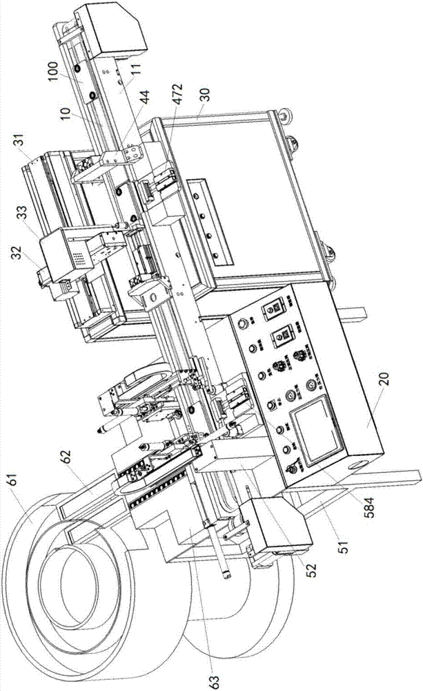
  • Figure 1
    Figure 1
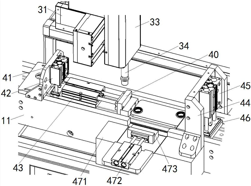
  • Figure 2
    Figure 2
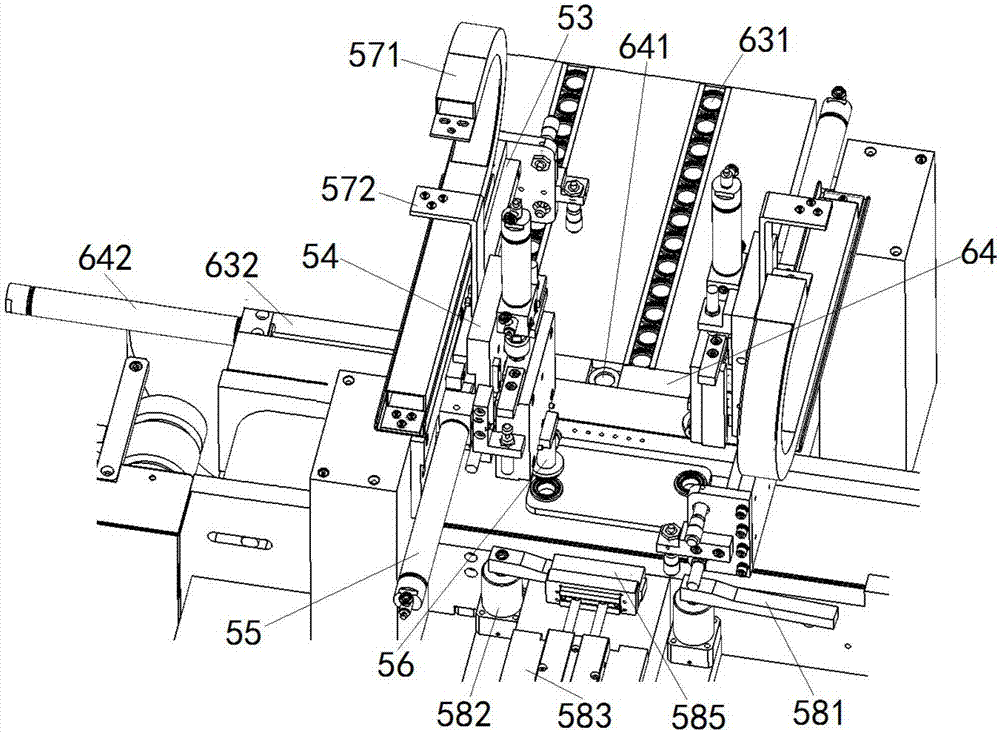
  • Figure 3
    Figure 3
Patent Text Reader

Abstract

The invention discloses an automated riveting device. The automated riveting device comprises a delivering belt, a polishing mechanism, a riveting mechanism, a feeding mechanism and a controlling mechanism, the polishing mechanism comprises a polishing table, an X-axis slide rail, a Y-axis slide rail, a lifting slide rail, a motor mounting plate, a polishing motor and a positioning component; the riveting mechanism comprises a riveting table, a riveting frame, a riveting motor, a horizontal slide rail, a longitudinal slide rail and a rotary pressing strip, the riveting motor is installed on a riveting bottom plate, and the riveting bottom plate is longitudinally and slidably arranged on the longitudinal slide rail; the feeding mechanism comprises a feeding disc, a connecting groove, a feed guiding plate and a feeding arm, and the feed guiding plate is provided with a feed guiding groove and a feeding groove which are horizontally formed and mutually vertically formed; the feeding groove is internally provided with a feeding strip, and the feeding strip is provided with a feed storage hole. The automated riveting device is compact in structure, can automatically load feed and unload feed, automatically conduct polishing and riveting, drastically lower the labor intensity of workers, and simplify the machining procedure, the riveting quality of an end plate is good, and the riveting efficiency is high.
Need to check novelty before this filing date? Find Prior Art

Description

technical field

[0001] The invention relates to the field of machinery, in particular to an automatic riveting device. Background technique

[0002] Bearings are widely used in the field of machining, and bearing components are important supporting components for various equipment connections. In many mechanical equipment, the two ends of the rotating shaft or the roller shaft need to be erected on the end plates on both sides through the bearings. In the process of production and processing, the bearings must be riveted to the end plates by riveting equipment first. After the bearings are riveted It must meet the positioning accuracy requirements and rotate flexibly. However, the traditional riveting operation has a low degree of automation. It is necessary to first open a through hole on the end plate through a hole opening device, then polish the inner wall of the through hole through a polishing device, and then manually place the end plate on the riveting table for fix...

Examples

Embodiment Construction

[0018] In order to make the technical means, creative features, goals and effects achieved by the present invention easy to understand, the present invention will be further described below in conjunction with specific embodiments.

[0019] see Figure 1 ~ Figure 3 , an automatic riveting device according to the present invention includes a conveyor belt 10 , a polishing mechanism, a riveting mechanism, a feeding mechanism and a control mechanism 20 .

[0020] The polishing mechanism includes a polishing table 30, an X-axis slide rail 31, a Y-axis slide rail 32, a lifting slide rail, a motor mounting plate, a polishing motor and a positioning assembly. The X-axis slide rail 31 is arranged on the polishing table 30 , and the conveyor belt 10 is arranged parallel to the X-axis slide rail 31 and its right end is erected on the polishing table 30 . The Y-axis slide rail 32 is horizontally slidably arranged on the X-axis slide rail 31 along the extension direction of the X-axis sl...