A flexible holding device for parts and assemblies of automobile stamping-welding production line

A welding production line and assembly technology, applied in the direction of motor vehicles, manufacturing tools, workpiece clamping devices, etc., can solve the problems of complex structure of switching drive mechanism, complex structure of holding mechanism, and decreased work efficiency, and achieve simple structure and flexibility Great effect with good applicability

Active Publication Date: 2019-07-23
CHONGQING UNIV
View PDF7 Cites 1 Cited by
  • Summary
  • Abstract
  • Description
  • Claims
  • Application Information

AI Technical Summary

Problems solved by technology

[0006] Although the flexible holding device of the automobile stamping-welding production line parts and assemblies of the automobile assembly parts conveying system can meet the lifting requirements of various parts assemblies of various models, the structure of the holding mechanism is complicated, and each There are only two support rods on the holding mechanism for positioning and cooperation with the workpiece to be lifted, so the applicability is limited. At the same time, the switching drive mechanism between the two support rods has a complicated structure and low switching efficiency, resulting in a decrease in work efficiency.

Method used


Image

  • A flexible holding device for parts and assemblies of automobile stamping-welding production line
  • A flexible holding device for parts and assemblies of automobile stamping-welding production line
  • A flexible holding device for parts and assemblies of automobile stamping-welding production line

Examples


Embodiment Construction

[0038] The present invention will be further described below in conjunction with the accompanying drawings and specific embodiments, so that those skilled in the art can better understand the present invention and implement it, but the examples given are not intended to limit the present invention.

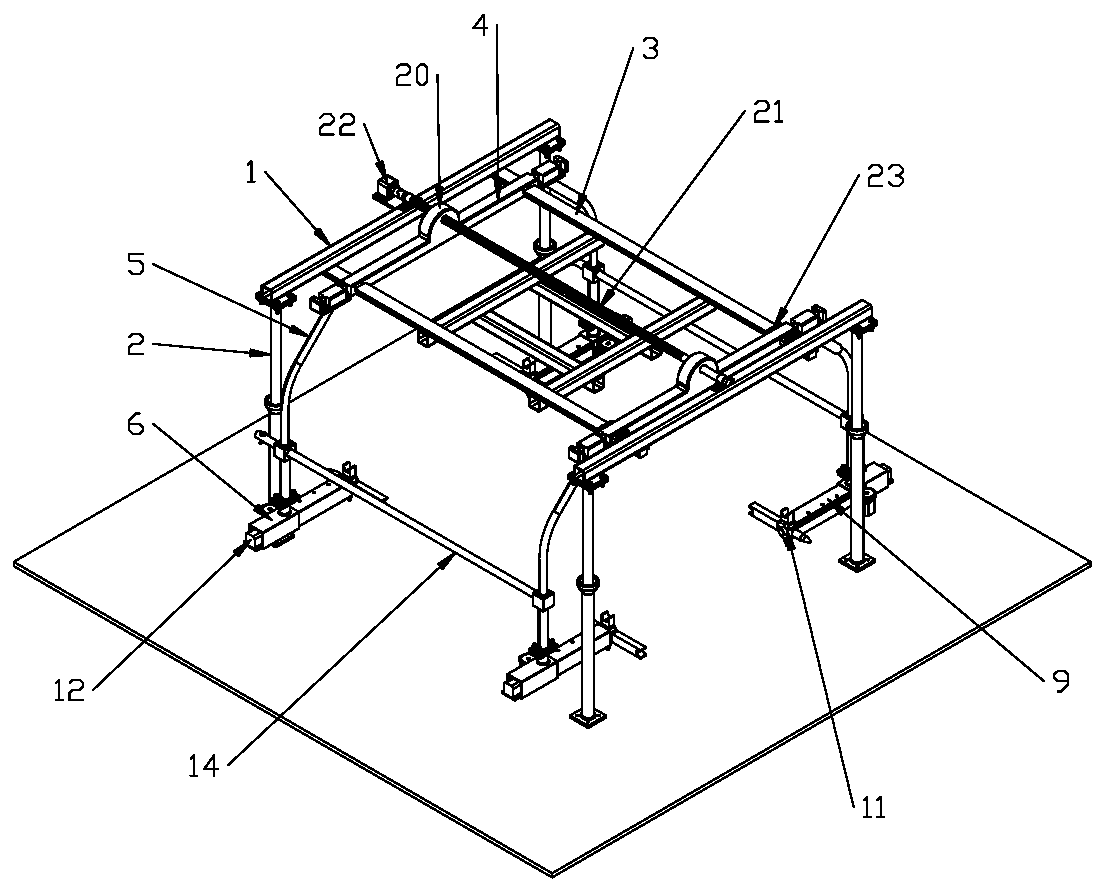
[0039] like figure 1 As shown, it is a structural schematic diagram of an embodiment of the flexible embrace of parts and assemblies of the automobile stamping-welding production line of the present invention. The flexible embrace of parts and assemblies of the automobile stamping-welding production line in this embodiment includes two load-bearing beams 1 parallel to each other, and support columns 2 are respectively provided at both ends of the load-bearing beams 1 . A slide rail 3 is provided between the two load beams 1, and at least two holding units are installed on the slide rail 3 in sliding fit with it. The slide rails 3 in this embodiment are arranged as two parallel to...


PUM


Abstract

The invention discloses a flexible holding tool for automobile stamping and welding production line parts and assemblies. The flexible holding tool comprises two parallel bearing beams, sliding rails are arranged between the two bearing beams, and at least two holding tool units are arranged on the sliding rails; the holding units comprise holding arm assemblies which are arranged on the sliding rails in a sliding fit mode; the holding arm assemblies comprise holding arms, connecting rods are arranged at the two ends of each holding arm, and supporting base assemblies are fixedly arranged on the connecting rods; the supporting base assemblies comprise supporting sleeves, sliding holes are formed in the supporting sleeves, a rail is arranged in each sliding hole, a telescopic cylinder is arranged on each rail in a sliding fit mode, and a telescopic driving mechanism is arranged on each supporting sleeve; a through hole is formed in each telescopic cylinder, a rotating shaft is arranged in each through hole, a positioning device is arranged at one end of each rotating shaft, and a switching motor used for driving the corresponding rotating shaft to rotate is arranged at the other end of each rotating shaft; each positioning device comprises a positioning block which synchronously rotates along with the corresponding rotating shaft, and at least two positioning piece mounting stations are annularly and uniformly distributed on each positioning block; the positioning piece mounting stations are detachably provided with positioning pieces used for being matched with a hoisted workpiece.

Description

technical field [0001] The invention belongs to the technical field of embraces, in particular to a flexible embrace for parts and assemblies of an automobile stamping-welding production line. Background technique [0002] like figure 1 As shown, it is a structural schematic diagram of an existing rigid conveying system for automobile assembly. The conveying system for automobile assembly generally includes a conveying track. Correspondingly, there are pre-stop points, and the holding device is slidably fitted and installed under the conveying track. The working process is as follows: the holding device stays at the pre-stop point for feeding, and moves into the top of the feeding point after receiving the signal that the front car group moves out. Then the spreader lowers, and the holding device grabs the parts; after the parts are sensed in place, the holding device clamps the parts, and then the spreader rises, and after rising in place, the spreader moves out of the loa...

Claims


Application Information

Patent Timeline
Patent Type & Authority Patents(China)
IPC IPC(8): B62D65/18B25B11/00
CPCB25B11/00
Inventor 杨波王彦凯王时龙唐倩周春
Owner CHONGQING UNIV
Why Eureka
Try Eureka