Blind separation hybrid matrix estimation method based on synchronous compression short-time Fourier transform

A short-time Fourier and synchronous compression technology, applied in computing, computer components, instruments, etc., can solve problems such as insufficient sparsity of complex mechanical signals, low energy aggregation of time-frequency transformation, and inability to correctly estimate the mixing matrix. Achieve the effects of improving energy aggregation, good estimation performance, and improving sparsity

Inactive Publication Date: 2017-10-27
XI AN JIAOTONG UNIV +1
View PDF0 Cites 7 Cited by
  • Summary
  • Abstract
  • Description
  • Claims
  • Application Information

AI Technical Summary

Problems solved by technology

However, for mechanical systems, it is difficult to ensure that all vibration signals have sparsity in the time domain and frequency domain, and the mixing matrix estimation methods based on the time-frequency domain are mostly based on STFT and wavelet transform. These traditional time-frequency The time-frequency transforma

Method used


Image

  • Blind separation hybrid matrix estimation method based on synchronous compression short-time Fourier transform
  • Blind separation hybrid matrix estimation method based on synchronous compression short-time Fourier transform
  • Blind separation hybrid matrix estimation method based on synchronous compression short-time Fourier transform

Examples


Embodiment 1

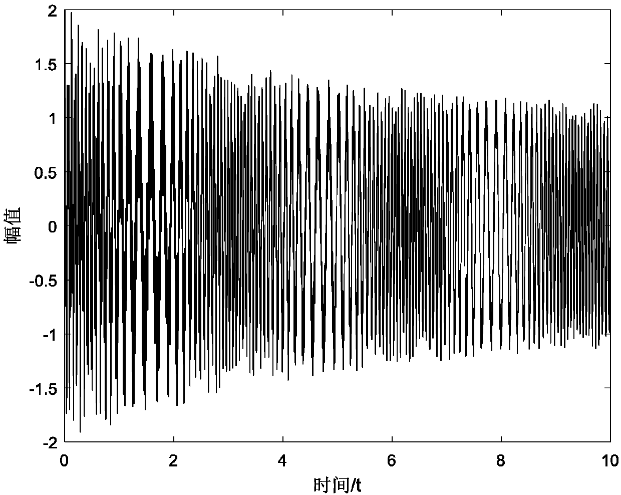
[0052] Embodiment 1, in order to illustrate the superiority of synchronous compression transform over traditional time-frequency transform, a simulation signal is selected, and its waveform diagram is as follows figure 1 shown. The expression of the simulation signal is: f(t)=cos{2π[0.1t 2 +3sin(2t)+10t]}+e -0.2t cos[2πt(40+t 1.3 )], the sampling time is 10s, and the sampling frequency is 200Hz. It can be seen from the expression that it consists of two parts, the frequency of one part is 0.1t+[3sin(2t)] / t+10, and the frequency of the other part is 40+t 1.3 , the frequencies of both parts vary with time.

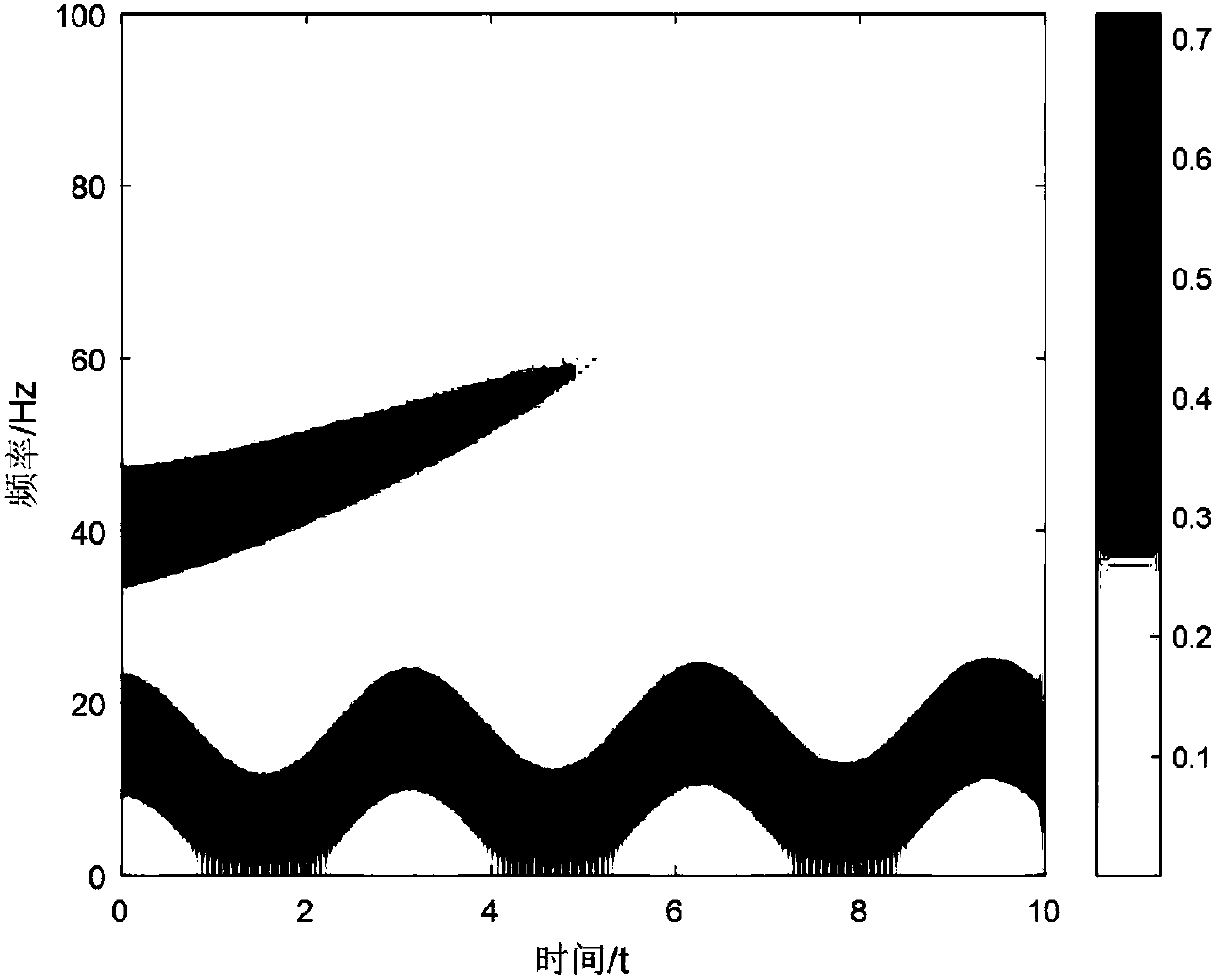
[0053] The simulated signal is subjected to STFT transformation, and the obtained time-frequency diagram is as follows: figure 2 As shown, the frequency is divided into two parts, but due to the low time-frequency aggregation, the readability is not strong.

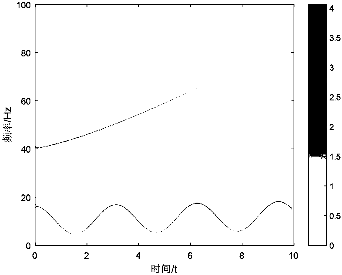
[0054] image 3 Shown is the time-frequency diagram obtained by the STFT synchronous compression transformati...

Embodiment 2

[0055] Embodiment 2, select 6 voice signals as the source signal, its waveform diagram is as follows Figure 4 As shown, although there is a certain sparsity in the time domain, the six speech signals overlap most of the time, that is, there are multiple speech signals at most time points. The original mixing matrix was chosen as follows: A = [0.2588, 0.7071, 0.9659, 0.9659, 0.7071, 0.2588; -0.9659, -0.7071, -0.2588, 0.2588, 0.7071, 0.9659].

[0056] Figure 5 Shown are the two observation signals obtained after the 6 speech signals in Example 2 pass through the original mixing matrix A, that is, at this time, there are 2 sensors in total, and the number of source signals is 6, which is underdetermined blind source separation In this case, the general overdetermined or well-posed blind source separation methods fail.

[0057] Under the condition of SNR=40dB, the window length is 1024, and the window moves 512 sampling points each time, the mixing matrix estimated by this met...


PUM


Abstract

The present invention discloses a blind separation hybrid matrix estimation method based on synchronous compression short-time Fourier transform. The purpose of the invention is to improve the sparsity of the time frequency domain of the observation signal, improve the energy of the useful signal, further reduce the influence of noise, and correctly estimate the hybrid matrix. Subjecting to STFT synchronous compression conversion, the observation signal is converted from the time domain to the time frequency domain, and the energy of each time frequency point in frequency is rearranged to improve the energy aggregation of the signal to be analyzed in the time frequency plane, thereby increasing the sparsity in the time frequency domain and reducing the effects of noise. In the process of extracting a single source point, a sparse coding method is used to search for a time frequency point corresponding to the only one non-zero element of coding coefficients, so as to search for time frequency points located in the same 1-D subspace. By minimizing the l1 norm of the coding coefficients and constructing the minimal objective function to extract the single source point, the noise suppression function is further enhanced. Finally, the hybrid matrix estimation is implemented by the hierarchical clustering method.

Description

technical field [0001] The invention relates to the field of mechanical vibration signal and acoustic radiation signal processing, in particular to a blind separation mixing matrix estimation method based on synchronously compressed short-time Fourier transform. Background technique [0002] The vibration and noise of the mechanical system have an important impact on the performance and safety of the system. For example, if the vibration of the submarine propulsion system is too large, it is easy to be discovered by the enemy and interfere with its own sonar detection. If the vibration of the rocket engine is too large, it is easy to cause the satellites and instruments it carries to be abnormal. work etc. Therefore, it is very important to find the source of vibration and noise and take measures to reduce its influence. The observation signal detected by the sensor is often the superposition of multiple vibration sources, and in view of the complexity of the mechanical sys...

Claims


Application Information

Patent Timeline
IPC IPC(8): G06K9/62G06K9/40
CPCG06V10/30G06V10/513G06F18/231G06F18/2321G06F18/2134
Inventor 成玮陆建涛陈建宏郝云胜訾艳阳何正嘉贺东曹宏瑞褚亚鹏谢劲松
Owner XI AN JIAOTONG UNIV
Why Eureka
Try Eureka