Speed change mechanism

A technology of speed change mechanism and linkage mechanism, applied in the direction of vehicle gearbox, mechanical equipment, gear transmission device, etc., can solve the problems of less gears and complex gearbox structure.

Inactive Publication Date: 2017-10-31
ENTROPY ZERO TECH LOGIC ENG GRP CO LTD
View PDF4 Cites 0 Cited by
  • Summary
  • Abstract
  • Description
  • Claims
  • Application Information

AI Technical Summary

Problems solved by technology

[0002] Speed ​​change mechanisms, such as gearboxes, are widely used in transmission systems. The current gearboxes have complex structures and few gears

Method used


Image

  • Speed change mechanism
  • Speed change mechanism
  • Speed change mechanism

Examples


Embodiment 1

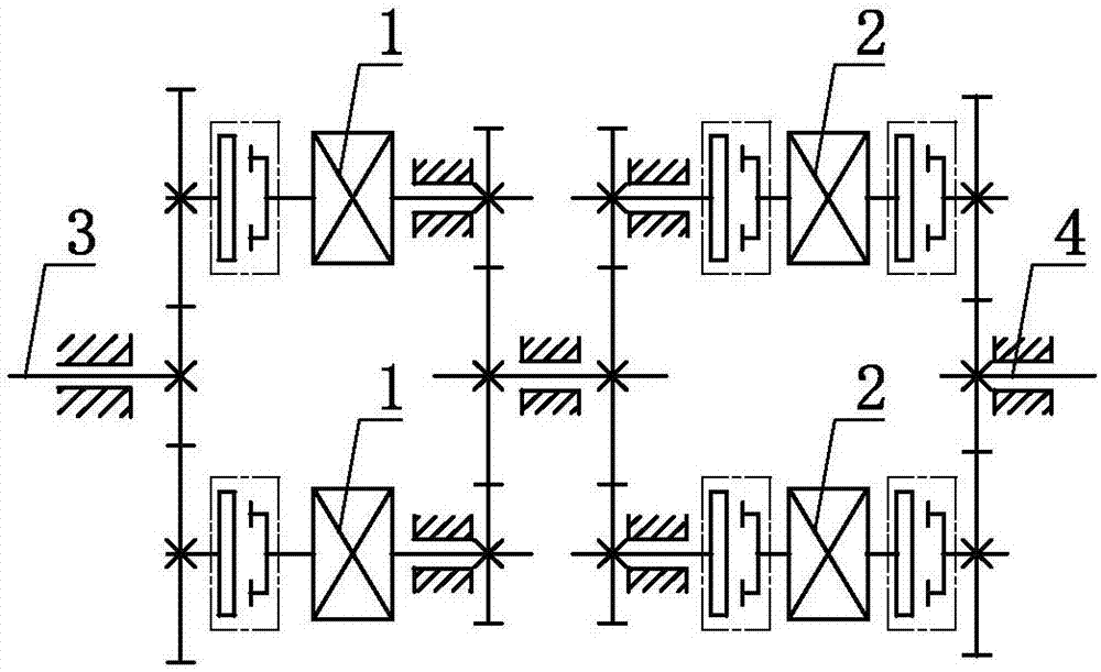
[0101] A speed change mechanism such as Figure 1.1 and 1.2 As shown, it includes two transmission units A 1, two transmission units B 2, a rotary power structure A 3 and a rotary power structure B 4, the transmission unit A 1 is not coaxially arranged, and the transmission unit B2 is non-coaxial axis setting, the transmission unit A 1 includes a power end AX and a power end AY, the transmission unit B 2 includes a power end BX and a power end BY, and the rotating power structure A 3 is set in transmission with the power end AX, The power end AY is set in transmission with the power end BX, the power end BY is set in transmission with the rotating power structure B4, and the rotating power structure A3 is set in clutch transmission with the power end AX, so The power end AY and the power end BX are arranged for clutch transmission, and the power end BY is arranged for clutch transmission with the rotating power structure B4.

[0102] As a changeable implementation mode, Examp...

Embodiment 2

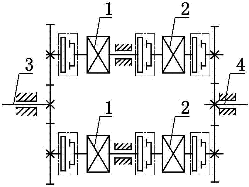
[0113]A speed change mechanism such as figure 2 As shown, it includes two transmission units A1, two transmission units B2, power wheel A5, power wheel B6 and power wheel AB7. The transmission unit A1 includes a power end AX and a power end AY. The transmission unit B2 includes a power end BX and a power end BY, the power end AX is set for clutch transmission with the power wheel A5, the power end AY is set for clutch transmission with the power wheel AB7, and the power end BX It is set with the power wheel AB 7 for clutch transmission, and the power end BY is set with the power wheel B 6 for clutch transmission.

[0114] As a changeable embodiment, Embodiment 2 of the present invention can further selectively make the speed change mechanism include three, four, five, six, seven, eight, nine, ten, ten One, twelve, thirteen, fourteen, fifteen, sixteen, seventeen, eighteen, nineteen or twenty transmission units A 1, and optionally further It is selected that two or more trans...

Embodiment 3

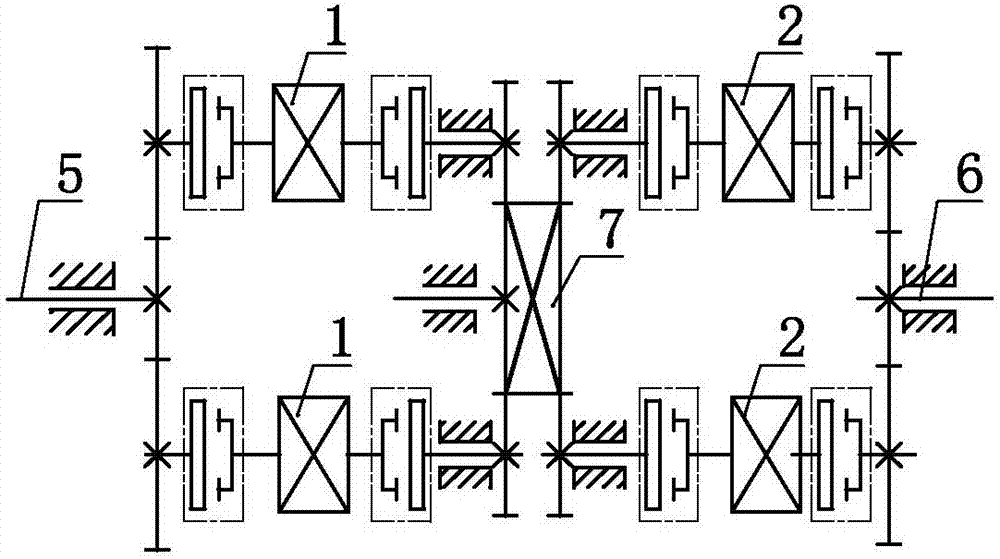
[0126] A speed change mechanism such as image 3 As shown, it includes two transmission units A1, two transmission units B2, power wheel A5, power wheel B6, power wheel N8 and power wheel M9, and the transmission unit A1 includes a power end AX and a power end end AY, the transmission unit B2 includes a power end BX and a power end BY, the power end AX is set for clutch transmission with the power wheel A5, and the power end AY is set for clutch transmission with the power wheel N8, The power end BX is set in clutch transmission with the power wheel M9, the power end BY is set in clutch transmission with the power wheel B6, and the power wheel N8 is set in mechanical connection with the power wheel M9.

[0127] As a changeable implementation mode, Embodiment 3 of the present invention can further selectively make the transmission mechanism include three, four, five, six, seven, eight, nine, ten, ten One, twelve, thirteen, fourteen, fifteen, sixteen, seventeen, eighteen, ninet...


PUM


Abstract

The invention discloses a speed change mechanism which comprises more than two driving units A, more than two driving units B, a rotating power structure A and a rotating power structure B, wherein the driving units A are arranged in a non-coaxial form; the driving units B are arranged in a non-coaxial form; each driving unit A comprises a power end AX and a power end AY; each driving unit B comprises a power end BX and a power end BY; the rotating power structure A and the power end AX are in driving arrangement; the power end AY and the power end BX are in driving arrangement; and the power end BY and the rotating power structure B are in driving arrangement. The speed change mechanism disclosed by the invention has the advantages of simple structure, multiple gear levels, high transmission efficiency, and the like.

Description

technical field [0001] The invention relates to the field of power and transmission, in particular to a speed change mechanism. Background technique [0002] Speed ​​change mechanisms, such as gearboxes, are widely used in transmission systems, and the current gearboxes have complex structures and few gears. Therefore, need to invent a kind of novel transmission mechanism. Contents of the invention [0003] In order to solve the above problems, the technical scheme proposed by the present invention is as follows: [0004] Scheme 1: A speed change mechanism, including two or more transmission units A, two or more transmission units B, a rotary power structure A and a rotary power structure B, the transmission unit A is not coaxially arranged, and the transmission unit B Non-coaxial arrangement, the transmission unit A includes a power end AX and a power end AY, the transmission unit B includes a power end BX and a power end BY, and the rotating power structure A and the p...

Claims


Application Information

Patent Timeline
Patent Type & Authority Applications(China)
IPC IPC(8): F16H3/44
CPCF16H3/44F16H3/006F16H2003/008F16H2200/2038
Inventor 靳北彪
Owner ENTROPY ZERO TECH LOGIC ENG GRP CO LTD
Why Eureka
Try Eureka