
Hardware machining device

A processing device and hardware technology, applied in metal processing equipment, metal processing mechanical parts, positioning devices, etc., can solve the problems of increased processing cost, high fixture cost, and many parameters to adjust, so as to improve work efficiency and improve processing. Quality, effect that is not easy to deviate

Pending Publication Date: 2017-11-03
江苏迎燕紧固系统科技有限公司
View PDF9 Cites 1 Cited by
  • Summary
  • Abstract
  • Description
  • Claims
  • Application Information

AI Technical Summary

Problems solved by technology

However, when processing the inclined surface of the product, such as processing the tableware with curved or inclined side walls or the side wall of the container, it is necessary to adjust the position of the processing tool so that it is perpendicular to the curved or inclined side wall. The best method is to use multi-axis linkage equipment adjustment, but the multi-axis equipment structure is relatively complex, and there are many parameters to adjust, and the actions are cumbersome, which greatly increases the processing cost and the efficiency is relatively low; at the same time, it is aimed at some small quantities Customized hardware, the cost of using customized fixtures is high, which is not conducive to the competitiveness of the product in the market. If it is made manually, the manufacturing cost will be extremely high, and the accuracy and product qualification rate will be greatly reduced.

Method used


Image

  • Hardware machining device
  • Hardware machining device
  • Hardware machining device

Examples


Embodiment Construction

[0021] Below in conjunction with specific embodiment, content of the present invention is described in further detail:

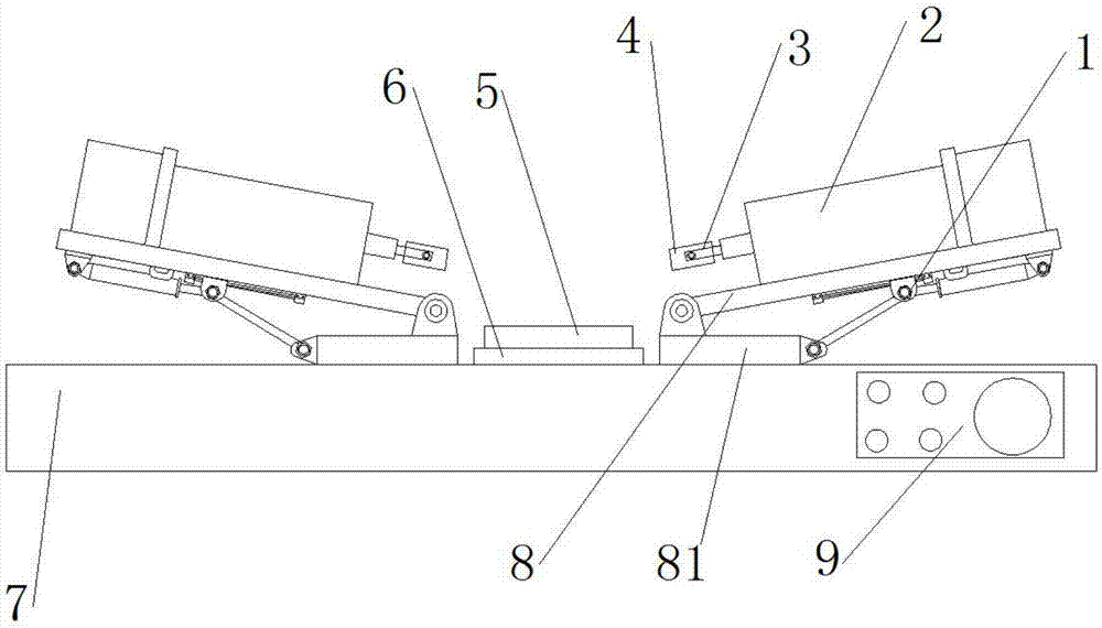
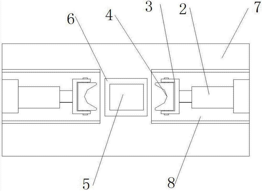
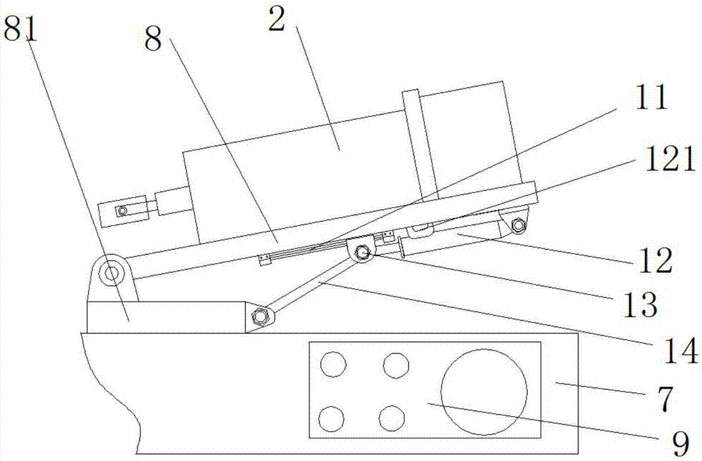
[0022] refer to figure 1 , figure 2 , image 3 , a hardware processing device, including a processing seat 8, one end of the processing seat 8 is hinged to a rotating shaft fixed on the bottom plate 81, a clamping device is provided on the processing seat 8, and a tilting device 1;

[0023] The tilting device 1 includes a slide rail 11, a lifting cylinder 12 and a support rod 14, limit blocks are provided at both ends of the slide rail 11, a connecting portion is provided at the cylinder end of the lifting cylinder 12, and the connecting portion of the cylinder seat The pin rod is connected with the cylinder seat arranged at the bottom of the processing seat 8, and the slide block 13 connected with the piston rod of the lifting cylinder 12 is slid on the slide rail 11 and hinged with the support rod 14. The other end of the support rod 14 is connected by...


PUM


Abstract

The invention relates to a hardware machining device which comprises a machining base. One end of the machining base is hinged to a rotary shaft fixed to a bottom plate. The machining base is provided with a clamping device, and tilting devices are arranged at the bottom of the machining base. Each tilting device comprises a sliding rail, a lifting air cylinder and a supporting rod, wherein limiting blocks are arranged at the two ends of the sliding rail; a connecting part is arranged at the tail end of a cylinder barrel of the lifting air cylinder; the air cylinder base connecting part is connected with an air cylinder base through a pin rod, and the air cylinder base is arranged at the bottom of the machining base; a sliding block connected with a piston rod of the lifting air cylinder is arranged on the sliding rail in a sliding mode and hinged to the supporting rod; and the other end of the supporting rod is hinged to a connecting part through pin rods, and the connecting part is fixed to the rear end of the bottom plate. The hardware machining method has the advantages of simple structure, safety, reliability, good stability and the like.

Description

technical field [0001] The invention relates to the technical field of hardware processing, in particular to a hardware processing device. Background technique [0002] In metal processing, it is necessary to clamp and process different workpieces to be processed. However, when processing the inclined surface of the product, such as processing the tableware with curved or inclined side walls or the side wall of the container, it is necessary to adjust the position of the processing tool so that it is perpendicular to the curved or inclined side wall. The best method is to use multi-axis linkage equipment adjustment, but the multi-axis equipment structure is relatively complex, and there are many parameters to adjust, and the actions are cumbersome, which greatly increases the processing cost and the efficiency is relatively low; at the same time, it is aimed at some small quantities For custom hardware, the cost of using custom fixtures is high, which is not conducive to th...

Claims


Application Information

Patent Timeline
Patent Type & Authority Applications(China)
IPC IPC(8): B23Q3/08
CPCB23Q3/08
Inventor 单艳芹
Owner 江苏迎燕紧固系统科技有限公司
Learn More