
Propulsion propeller and pneumatic ship not likely to roll over during high-speed navigation

A technology for propellers and ships, which is applied in the direction of rotating propellers, ship propulsion, ship parts, etc., can solve the problems of high use cost, large resistance, high resistance, etc., and achieve the effect of reasonable design, reduced resistance and small water splash

Pending Publication Date: 2017-11-03
胡斌
View PDF0 Cites 0 Cited by
  • Summary
  • Abstract
  • Description
  • Claims
  • Application Information

AI Technical Summary

Problems solved by technology

[0002] At present, during the use of the existing ship propeller structure, the agitated water splash is relatively large, the resistance is high, and the corresponding energy consumption is relatively high; It is relatively large, and the cost of use is relatively high. The resistance of existing ships is relatively large when the bottom of the ship is submerged in the water during operation, which is not conducive to energy saving and environmental protection

Method used


Image

  • Propulsion propeller and pneumatic ship not likely to roll over during high-speed navigation
  • Propulsion propeller and pneumatic ship not likely to roll over during high-speed navigation
  • Propulsion propeller and pneumatic ship not likely to roll over during high-speed navigation

Examples


Embodiment 1

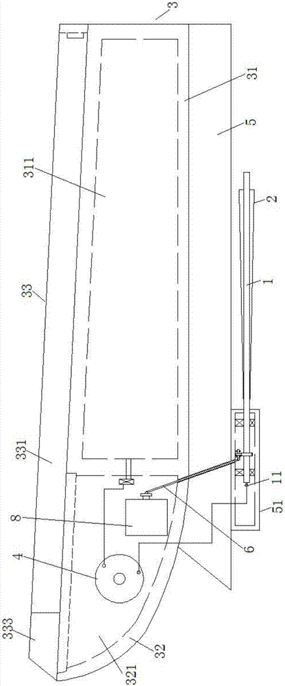
[0043] Embodiment one: if figure 1 As shown, this embodiment provides a propulsion propeller, which is characterized in that: it includes a main shaft 1 and at least three blades 2 with the same specifications;

[0044] At least three of the above-mentioned blades 2 are circumferentially and evenly arranged on the outer periphery of the main shaft 1, and extend circumferentially from a position close to one end of the above-mentioned main shaft 1 to a position close to the other end thereof, and the cross-section of each of the above-mentioned blades 2 is arc-shaped, And the distance between the edge of each blade 2 on the side away from the main shaft 1 and the axis of the main shaft 1 gradually increases from one end of the main shaft 1 to the other end.

[0045]During use, the main shaft 1 of the propeller is driven by the driving mechanism of the ship to rotate. Since the blades 2 are arranged along the axial direction of the main shaft 1, and the cross-sectional area grad...

Embodiment 2

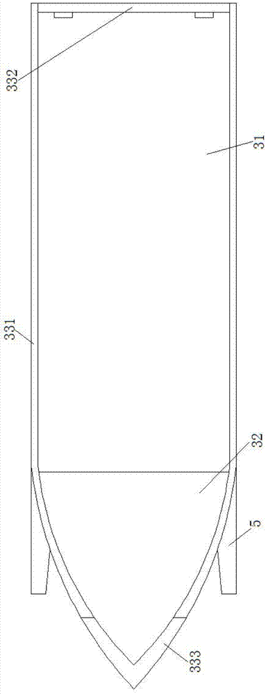
[0048] Embodiment two: if Figure 2-6 As shown, the present embodiment provides an aerodynamic boat that is not prone to rollover during high-speed navigation, including a hull 3, two air generators 4, two propulsion propellers and two universal joint transmission shafts 6;

[0049] Above-mentioned hull 3 is made of integrally formed hull 31 and bow 32;

[0050] Both sides of the bottom of the above-mentioned hull 31 are symmetrically provided with two accumulation wings 5, the front end of each of the above-mentioned accumulation wings 5 ​​all extends to the above-mentioned bow 32, and the rear end extends to be flush with the rear end of the above-mentioned hull 31 ;

[0051] The lower end of the front end of each of the above-mentioned backlog wings 5 ​​is integrally formed with an internal hollow connection portion 51, and the two above-mentioned propulsion propellers are arranged in one-to-one correspondence with the two above-mentioned connection portions 51, and each o...


PUM


Abstract

The invention relates to a pneumatic ship not likely to roll over during high-speed navigation. The pneumatic ship comprises a ship body, two pneumatic machines, two propulsion propellers and two universal joint transmission shafts. Two backlog wings are symmetrically arranged on the two sides of the bottom of the ship body. The lower end of the front end of each backlog wing is provided with a hollow connection portion in an integrally-formed mode. The two propulsion propellers are in one-to-one correspondence with the two connection portions. The propulsion propellers are arranged behind the connection portions correspondingly, and one end of a main shaft stretches into the corresponding connection portion. A high-pressure gas storage bin is arranged in the ship body. An assembling chamber is arranged in a nose. The two pneumatic machines are installed in the assembling chamber and are in one-to-one correspondence with the two connection portions. Each pneumatic machine is provided with an air inlet and an air outlet, and the air inlet of each pneumatic machine communicates with an air outlet of the high-pressure gas storage bin. One end of each universal joint transmission shaft is connected with the output end of the corresponding pneumatic machine, and the other end of each universal joint transmission shaft stretches into the corresponding connection portion to be connected with one end of the main shaft. The pneumatic ship has the advantages of being reasonable in design, small in advancing resistance, capable of saving energy, environmentally friendly and extremely good in high-speed navigation stability.

Description

technical field [0001] The invention relates to the technical field of ship manufacturing, in particular to a propulsive propeller and an aerodynamic ship which is difficult to rollover when sailing at high speed. Background technique [0002] At present, during the use of the existing ship propeller structure, the agitated water splash is relatively large, the resistance is high, and the corresponding energy consumption is relatively high; It is relatively large, and the cost of use is relatively high. The resistance of the existing ships is relatively large when the bottom of the ship is submerged in the water during operation, which is not conducive to energy saving and environmental protection. Contents of the invention [0003] The technical problem to be solved by the present invention is to provide a propelling propeller and an aerodynamic ship equipped with it, which is not easy to roll over at high speed, which effectively overcomes the defects of the prior art. ...

Claims


Application Information

Patent Timeline
Patent Type & Authority Applications(China)
IPC IPC(8): B63H1/26B63H11/12
CPCB63H1/26B63H11/12
Inventor 胡斌
Owner 胡斌
Learn More