Leading edge load mounting system of flying wing stealth unmanned aerial vehicle

A technology for installing systems and drones, applied in the field of drones, can solve the problems of inconvenient installation of stealth aircraft loads, inability to reflect radar waves, etc., and achieve the effect of reducing reflection and ensuring stealth performance

Pending Publication Date: 2017-11-03
西安天拓航空科技有限公司
View PDF6 Cites 5 Cited by
  • Summary
  • Abstract
  • Description
  • Claims
  • Application Information

AI Technical Summary

Problems solved by technology

[0003] The present invention proposes a leading-edge load installation system for stealth drones with flying wing layo

Method used


Image

  • Leading edge load mounting system of flying wing stealth unmanned aerial vehicle
  • Leading edge load mounting system of flying wing stealth unmanned aerial vehicle

Examples


Embodiment Construction

[0019] The present invention will be explained and described in detail below in conjunction with the accompanying drawings and specific embodiments.

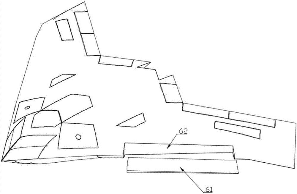
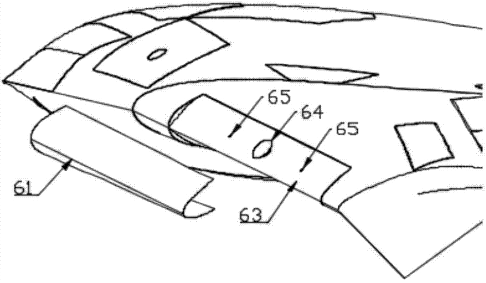
[0020] like figure 1 and figure 2 As shown, the leading edge load installation system of the flying wing layout stealth UAV includes a concave installation gap arranged on the leading edge of the wing, a front beam 62, a leading edge wedge 63 and a leading edge load hatch 61, and a front beam 62 Installed at the bottom of the installation gap, the leading edge wedge 63 is arranged on the front beam 62 and covers the front beam 62, the leading edge load hatch 61 is installed on the leading edge wedge 63 and smoothly transitions with the fuselage, and the leading edge wedge 63 is provided with a mounting hole 65 for installing the load 64. The leading edge wedge 63 is wedge-shaped protruding outwards and forms a V-shaped cavity with the leading edge load hatch 61. The leading edge wedge 63 Adopt conductive materials, such as: f...


PUM


Abstract

The invention relates to the field of unmanned aerial vehicles, in particular to a leading edge load mounting system of a flying wing stealth unmanned aerial vehicle. The leading edge load mounting system aims at solving the problem that a stealth aircraft cannot reflect radar waves because of inconvenient load mounting. The leading edge load mounting system of the flying wing stealth unmanned aerial vehicle comprises a concave mounting notch formed in the leading edge of a wing, a front spar, a leading edge wedge and a leading edge load hatch cover. The front spar is installed at the bottom of the mounting notch. The leading edge wedge is arranged on the front spar and covers the front spar. The leading edge load hatch cover covers the leading edge wedge and is in smooth transition with the body of the unmanned aerial vehicle. A mounting hole for mounting a load is formed in the leading edge wedge which is made of a conductive material and is in a convex wedge shape. A V-shaped cavity is formed between the leading edge wedge and the leading edge load cover. The leading edge load hatch cover is made of a wave-transmitting material. A load system has the capacity of carrying a built-in reflector, and can simulate all imaginary targets without affecting aerodynamic configuration.

Description

technical field [0001] The invention relates to the field of unmanned aerial vehicles, in particular to a leading edge load installation system for a stealth unmanned aerial vehicle with flying wing layout. Background technique [0002] The loads of existing UAVs can be generally divided into three types: installation in the belly, hanging under the belly, and hanging under the wings. However, there are many inconveniences for UAVs that have strict requirements on appearance, such as unmanned observation drones that require stealth. When it is necessary to mount a specific radar reflector, on the one hand, it is necessary to ensure the shape of the aircraft, and the reflector cannot be mounted outside the aircraft; on the other hand, the stealth aircraft is made of high-conductivity materials, and the reflector installed in the belly will Due to electromagnetic shielding, the purpose of reflecting radar waves cannot be achieved. Contents of the invention [0003] The inv...

Claims


Application Information

Patent Timeline
IPC IPC(8): B64D47/02
CPCB64D47/02B64U10/25B64U20/10
Inventor 不公告发明人
Owner 西安天拓航空科技有限公司
Why Eureka
Try Eureka