
An axial flow wind wheel and an air conditioner with the same

An axial-flow wind and hub technology, which is applied to the components of pumping devices for elastic fluids, machines/engines, non-variable-capacity pumps, etc. The effect of reducing blade weight, reducing leading edge resistance and reducing leakage vortex

Active Publication Date: 2017-11-03
GD MIDEA AIR-CONDITIONING EQUIP CO LTD
View PDF6 Cites 11 Cited by
  • Summary
  • Abstract
  • Description
  • Claims
  • Application Information

AI Technical Summary

Problems solved by technology

[0002] In related technologies, most of the air conditioners use axial-flow wind rotors for heat dissipation. The axial-flow wind rotors include two or more blades arranged on the hub. Distributed on the hub, when the axial flow wind turbine with conventional blade structure rotates, it is easy to cause the accumulation of low-energy fluid on the suction surface of the blade, and form a large vortex on the suction surface of the blade, resulting in a higher wind turbine during operation. aerodynamic noise

Method used


Image

  • An axial flow wind wheel and an air conditioner with the same
  • An axial flow wind wheel and an air conditioner with the same
  • An axial flow wind wheel and an air conditioner with the same

Examples


Embodiment Construction

[0029] Embodiments of the invention are described in detail below, examples of which are illustrated in the accompanying drawings. The embodiments described below by referring to the figures are exemplary and are intended to explain the present invention and should not be construed as limiting the present invention.

[0030] In the description of the present invention, it should be understood that the terms "center", "length", "inner", "outer", "axial", "radial", "circumferential" and the like indicate the orientation or positional relationship Based on the orientation or positional relationship shown in the drawings, it is only for the convenience of describing the present invention and simplifying the description, and does not indicate or imply that the referred device or element must have a specific orientation, be constructed and operated in a specific orientation, and therefore cannot be construed as a limitation of the invention.

[0031] In addition, the terms "first" ...


PUM


Abstract

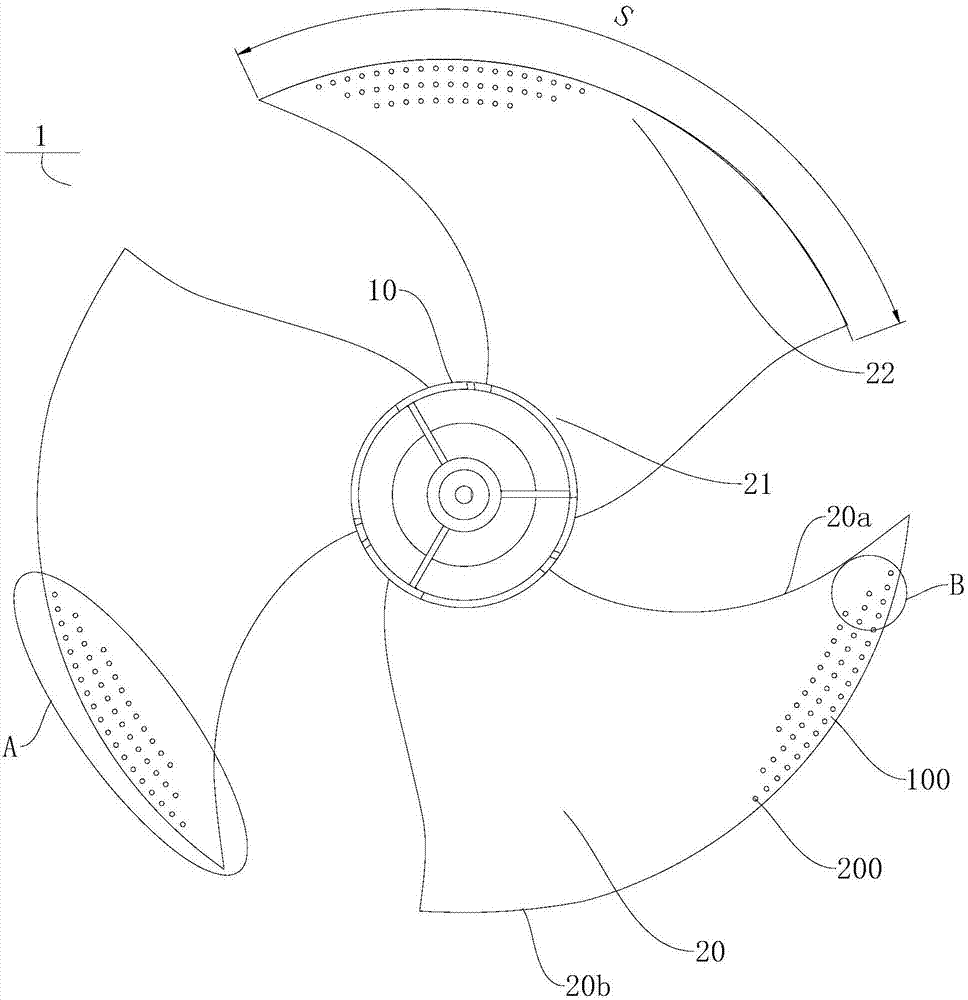
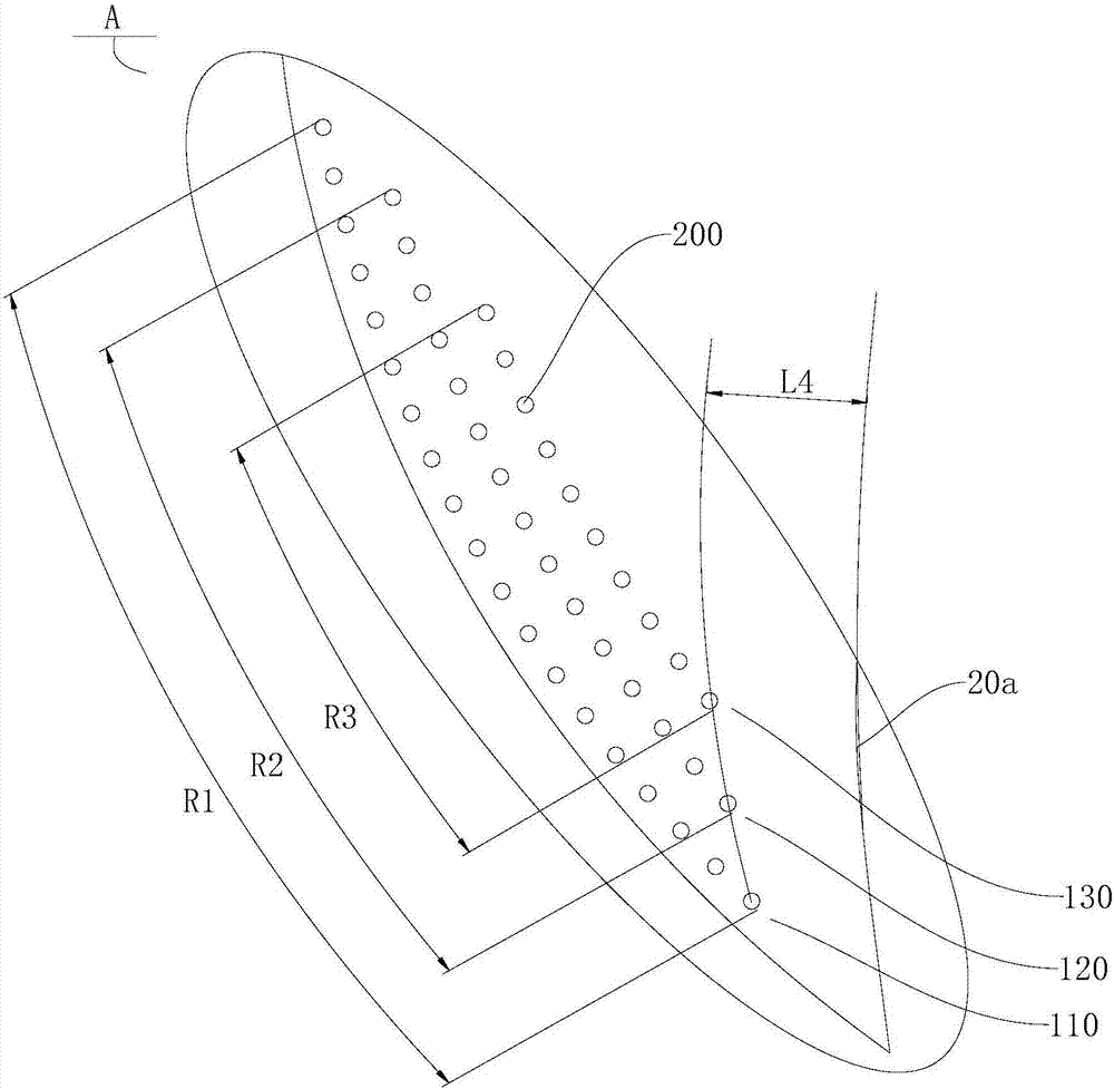
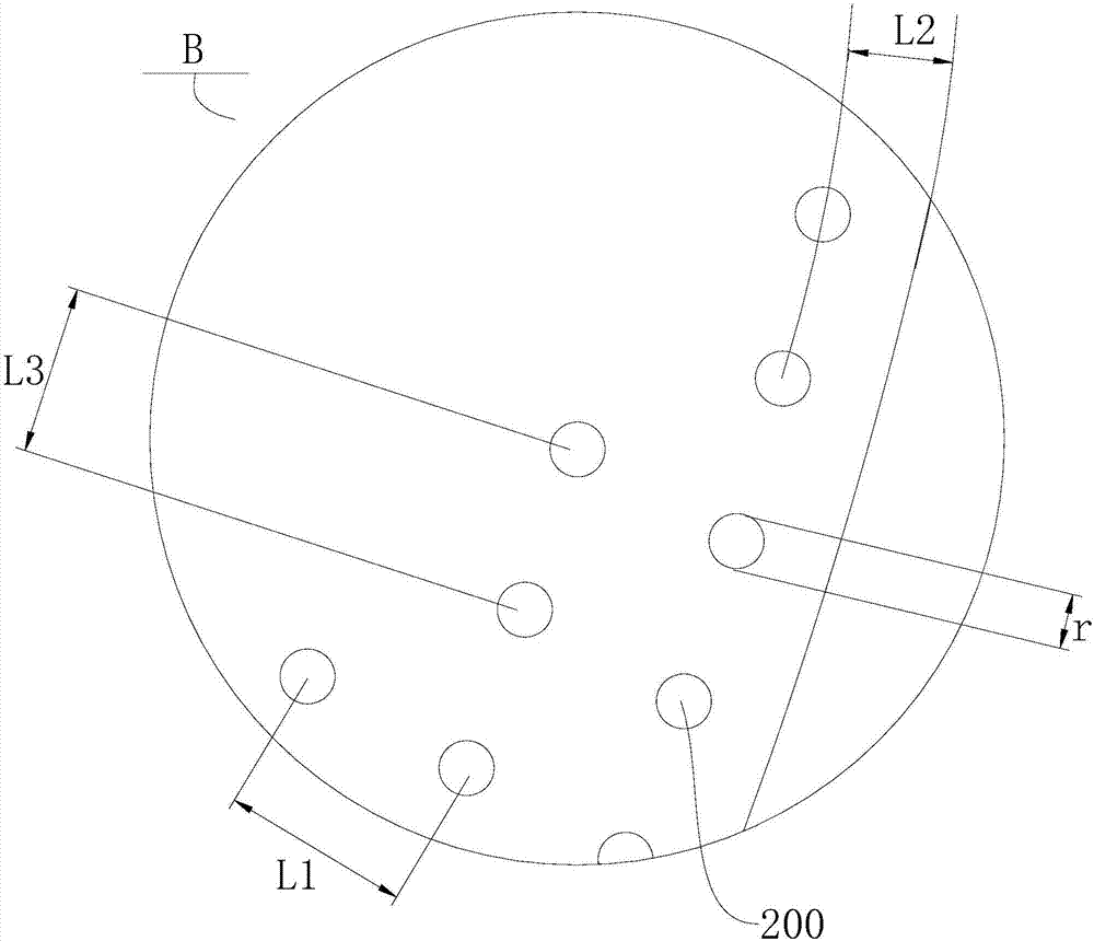
The invention provides an axial flow wind wheel and an air conditioner with the same. The axial flow wind wheel comprises a hub and a plurality of blades distributed in the circumferential direction of the hub in a spaced manner; each blade is connected with the hub; the position close to the outer edge of each blade is provided with multiple hole groups, which are distributed in the radial direction of the hub in a spaced manner; each hole group comprises a plurality of mutually-spaced through holes; the through holes are arranged in the circumferential direction of the hub. The axial flow wind wheel has the advantages that the outer edge positions of the blades are provided with the multiple hole groups, so that part of air flow of a pressure surface of each blade can flow to a suction surface via the hole groups directly, air flow flowing from the outer edge of the pressure surface of each blade to the suction surface is reduced, leaking vortexes generated at the outer edges of the suction surfaces can be reduced and eddy current noise of the axial flow wind wheel can be reduced; with the hole groups, the weight of the blades can be reduced, so that the front edge resistance of the blades can be reduced and the motor power of an air conditioner can be reduced.

Description

technical field [0001] The invention relates to the technical field of refrigeration, in particular to an axial flow wind wheel and an air conditioner with the same. Background technique [0002] In related technologies, most of the air conditioners use axial-flow wind rotors for heat dissipation. The axial-flow wind rotors include two or more blades arranged on the hub. Distributed on the hub, when the axial flow wind turbine with conventional blade structure rotates, it is easy to cause the accumulation of low-energy fluid on the suction surface of the blade, and form a large vortex on the suction surface of the blade, resulting in a higher wind turbine during operation. Aerodynamic noise. According to experimental analysis, 50%-70% of the noise of the air conditioner is caused by the aerodynamic noise of the axial flow wind wheel. Contents of the invention [0003] The present invention aims to solve one of the technical problems in the related art to a certain extent...

Claims


Application Information

Patent Timeline
IPC IPC(8): F04D29/32F04D29/38F04D29/66F04D29/68
CPCF04D29/325F04D29/388F04D29/667F04D29/681F04D29/682F04D29/684F04D29/384F05D2240/307
Inventor 黄愉太蔡序杰
Owner GD MIDEA AIR-CONDITIONING EQUIP CO LTD
Learn More