Crushing device for foodstuff processing machine and foodstuff processing machine
A technology for food processing machines and crushing devices, applied in applications, household appliances, kitchen appliances, etc., can solve the problems of high cost, inability to enter the grinding disc to be ground, and inability to realize slurry circulation cutting and grinding.
- Summary
- Abstract
- Description
- Claims
- Application Information
AI Technical Summary
Problems solved by technology
Method used
Image
Examples
Embodiment 1
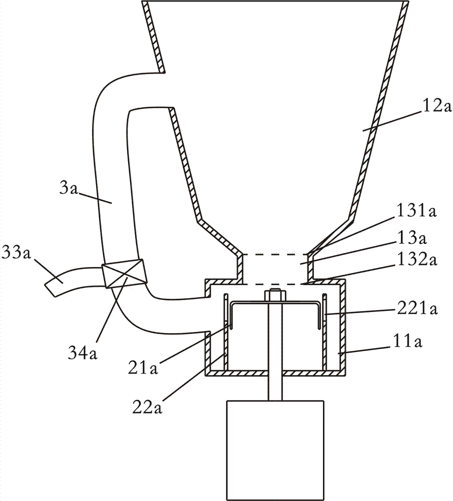
[0049] Such as figure 1 Shown is a schematic structural diagram of the first embodiment of the present invention. A food processing machine, the crushing device of the food processing machine includes a container 1, a crushing blade 2 arranged in the container 1 and a circulation pipeline 3 connecting the container up and down, the crushing blade 2 is driven by a motor 4, and the The circulation pipeline 3 is arranged outside the container, and the container 1 includes a crushing chamber 11 located at the bottom of the container, a return chamber 12 located above the crushing chamber 11, and a converging port 13 connecting the crushing chamber 11 and the return chamber 12. The blade 2 is arranged in the crushing chamber 11, and the gathering port 13 is arranged above the crushing blade 2, the inlet 31 of the circulation pipeline is located in the crushing chamber 11, and the outlet 32 of the circulation pipeline is located in the return chamber 12 Inside.
[0050] The food...
Embodiment 2
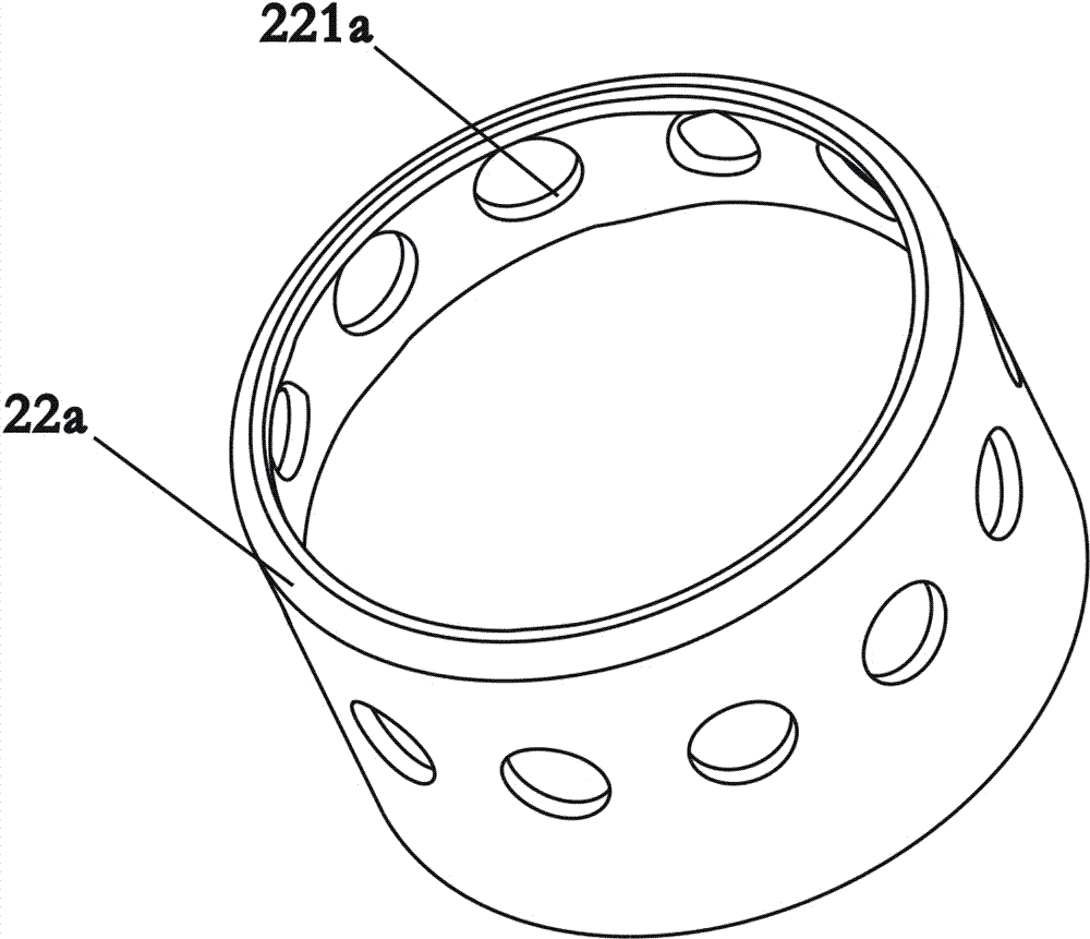
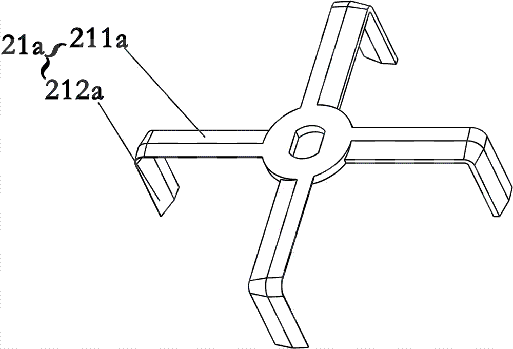
[0054] Such as figure 2 , image 3 Shown is a schematic structural diagram of the second embodiment of the present invention. The difference from Embodiment 1 is that the food processing machine in this embodiment has a structure with a motor under it, and the flow-gathering port 13 is tubular, and the flow-gathering port 13 has a water inlet 131 and a water outlet 132. The water inlet 131 is located in the return chamber 12 , and the water outlet 132 is located in the crushing chamber 11 . Moreover, the circulation pipeline 3 is provided with a slurry outlet 33 and a control valve 34, the slurry outlet 33 communicates with the circulation pipeline 3, and the control valve 34 is used to control the slurry outlet 33 to output the slurry, and to control The valve 34 is arranged between the slurry nozzle 33 and the circulation pipeline 3 . By setting the control valve 34 and the slurry outlet 33 , after the pulping is completed, the user can directly control the control valve...
Embodiment 3
[0060] Such as Figure 4 , Figure 5 , Figure 6 Shown is a schematic structural view of the third embodiment of the present invention. The difference from Embodiment 2 is that in this embodiment, the bottom of the recirculation cavity 12 has a converging portion 14 that protrudes toward the center of the container, and the top surface of the converging portion 14 is inclined downward relative to the horizontal plane. 14 The inclination angle α relative to the horizontal plane is generally less than 80°. Since the converging part 14 is in the shape of an inverted cone, the backflowing material and slurry can be collected, making it easier for the material to flow in from the converging port. At the same time, the top of the crushing chamber 11 is provided with a shielding part 15 that limits the material in the crushing chamber 11 (the shielding part 15 can further prevent the material from being ejected from the crushing chamber 11 after being collided by the crushing blad...
PUM
 Abstract
Description
Claims
Application Information
 - R&D
- Intellectual Property
- Life Sciences
- Materials
- Tech Scout
- Unparalleled Data Quality
- Higher Quality Content
- 60% Fewer Hallucinations
Browse by: Latest US Patents, China's latest patents, Technical Efficacy Thesaurus, Application Domain, Technology Topic, Popular Technical Reports.
© 2025 PatSnap. All rights reserved.Legal|Privacy policy|Modern Slavery Act Transparency Statement|Sitemap|About US| Contact US: help@patsnap.com


