Brittle material acid pickling frame

A brittle material, pickling technology, applied in the direction of chemical instruments and methods, cleaning methods and utensils, cleaning methods using liquids, etc., can solve the problems of surface cleanliness of parts, difficult to master the process, easy to damage parts, etc., to achieve cleaning The time is consistent, the cleaning effect is good, and the cleaning effect is uniform

Pending Publication Date: 2017-11-07
北京亦盛精密半导体有限公司
View PDF8 Cites 3 Cited by
  • Summary
  • Abstract
  • Description
  • Claims
  • Application Information

AI Technical Summary

Problems solved by technology

[0003] The existing technical condition is to use a clamp similar to tweezers with a large contact area to transfer parts. Since this process is a direct transfer of parts by humans, it is necessary to control the clamping force well. The process is not easy to master, and parts may be broken or the risk of bumping, and the clip has a large contact with the surface of the part, and the part needs to be turned over during the chemical reaction, which is easy to affect the cleanliness of the part surface
A kind of cleaning basket is also designed in the prior art, and the parts are put into the cleaning basket to be loaded and cleaned in batches. If the slot is too tight, the parts will be easily damaged when placed and taken out. If the slot is too loose, the parts will inevitably shake and rub with the cleaning basket during cleaning, causing damage to the surface of the parts.
Moreover, no matter whether it is manually clamped or placed in the existing cleaning basket, the parts generally enter and exit the cleaning pool vertically. For the cleaning process whose cleaning time is accurate to seconds, the cleaning time at the bottom of the parts must be Obviously longer than the cleaning time of the upper part, so it will cause uneven cleaning of the surface of the parts

Method used


Image

  • Brittle material acid pickling frame
  • Brittle material acid pickling frame

Examples


Embodiment Construction

[0017] The present invention and the technical solutions in the embodiments of the present invention will be clearly and completely described below in conjunction with the accompanying drawings.

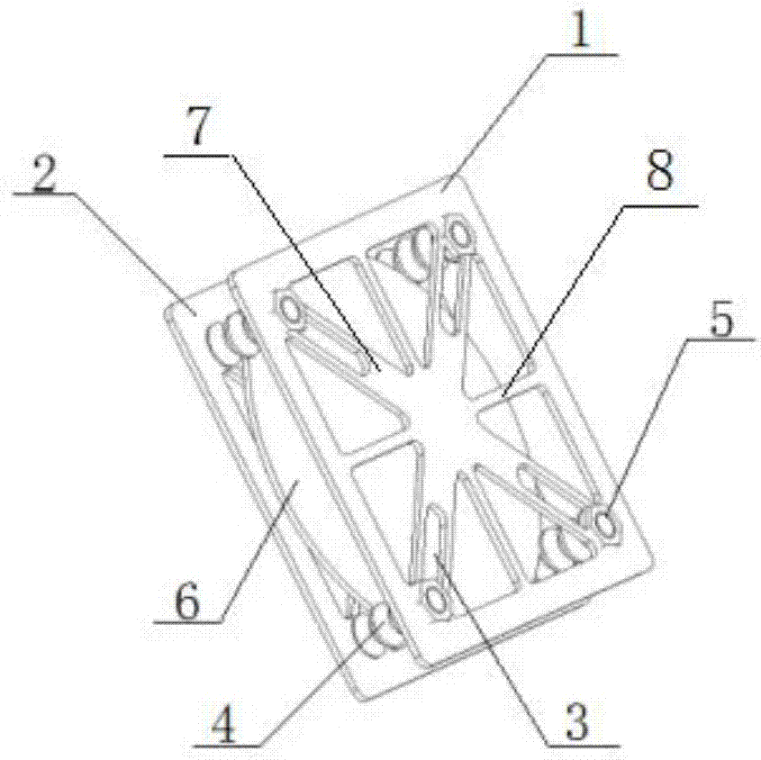
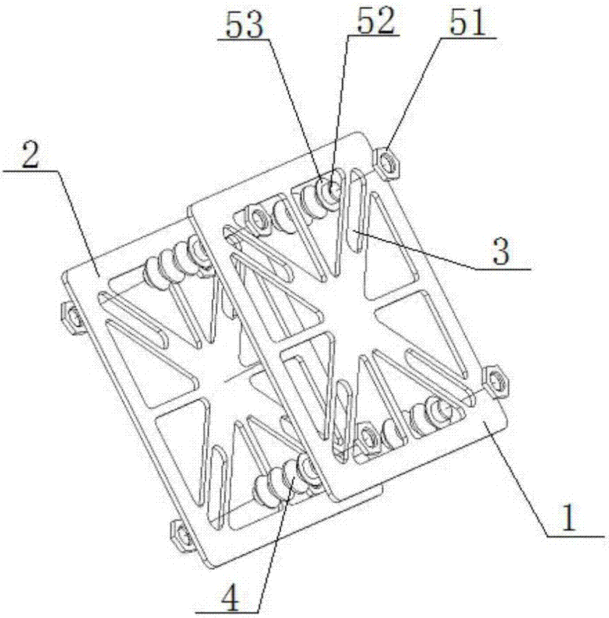
[0018] Such as Figure 1-2 , including two rectangular front support frames 1 and rear support frames 2, the front support frame 1 and the rear support frame 2 are placed in parallel and at intervals, and four fixing rods 4 are vertically arranged between the front support frame 1 and the rear support frame 2, The two ends of the fixed rod 4 are slidably connected to the front support frame 1 and the rear support frame 2 respectively, and the sliding routes of the ends of the fixed rod 4 connected with the front support frame 1 are respectively arranged from the center of the front support frame 1 to the four top corners. On the four connecting lines, the sliding routes of the ends of the fixed rod 4 connected to the rear support frame 2 are respectively arranged on the four connecti...


PUM


Abstract

The invention discloses a brittle material acid pickling frame. The brittle material acid pickling frame comprises a front support and a rear support which are both rectangular; four fixing rods are arranged between the front support and the rear support; the two ends of the fixing rods are slidably connected to the front support and the rear support correspondingly; the sliding paths of the ends, connected to the front support, of the fixing rods are located on the connecting lines from the center to the four top corners of the front support correspondingly; the sliding paths of the ends, connected to the rear support, of the fixing rods are located on the connecting lines from the center to the four top corners of the rear support correspondingly; the middle of each fixing rod is provided with at least one annular clamping groove; and the brittle material acid pickling frame further comprises locking devices used for locking the ends of the fixing rods. The periphery of a part is uniformly fixed through the fixing rods of the acid pickling frame, and the part cannot slide out in any direction or shake and can be more stably clamped; the part can be horizontally placed in a cleaning pool when being cleaned, is suspended in the air and is prevented from being bumped and damaged; and the cleaning time of all portions of the part is consistent, cleaning is uniform, and the cleaning effect is good.

Description

technical field [0001] The invention belongs to the technical field of automatic cleaning carrying equipment, and in particular relates to a brittle material pickling frame. Background technique [0002] Chemical cleaning is a necessary part of surface cleaning in industrial production. Because it involves chemicals and chemical reactions, the process is unstable and dangerous. Chemical cleaning materials are divided into two categories, one is ordinary materials, and the other is It is a special material. The chemical cleaning of ordinary materials can be clamped or held by some common fixtures or holding frames. For special materials, especially brittle materials such as silicon and other brittle materials, they must be clamped firmly , but not too hard to prevent bumps or chipping due to excessive stress, thereby damaging the integrity of the material or parts, and during the entire process, the parts should have as little contact with other factors as possible to avoid c...

Claims


Application Information

Patent Timeline
Patent Type & Authority Applications(China)
IPC IPC(8): B08B3/08B08B13/00
CPCB08B3/08B08B13/00
Inventor 王孟冯雨雨袁林锋
Owner 北京亦盛精密半导体有限公司
Why Eureka
Try Eureka