Cutter template sewing machine
A sewing machine and cutter technology, which is applied to sewing machine components, sewing machine control devices, sewing equipment, etc., can solve the problems of template turning, inability to process, and small processing range.
- Summary
- Abstract
- Description
- Claims
- Application Information
AI Technical Summary
Problems solved by technology
Method used
Image
Examples
Embodiment 1
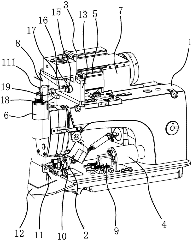
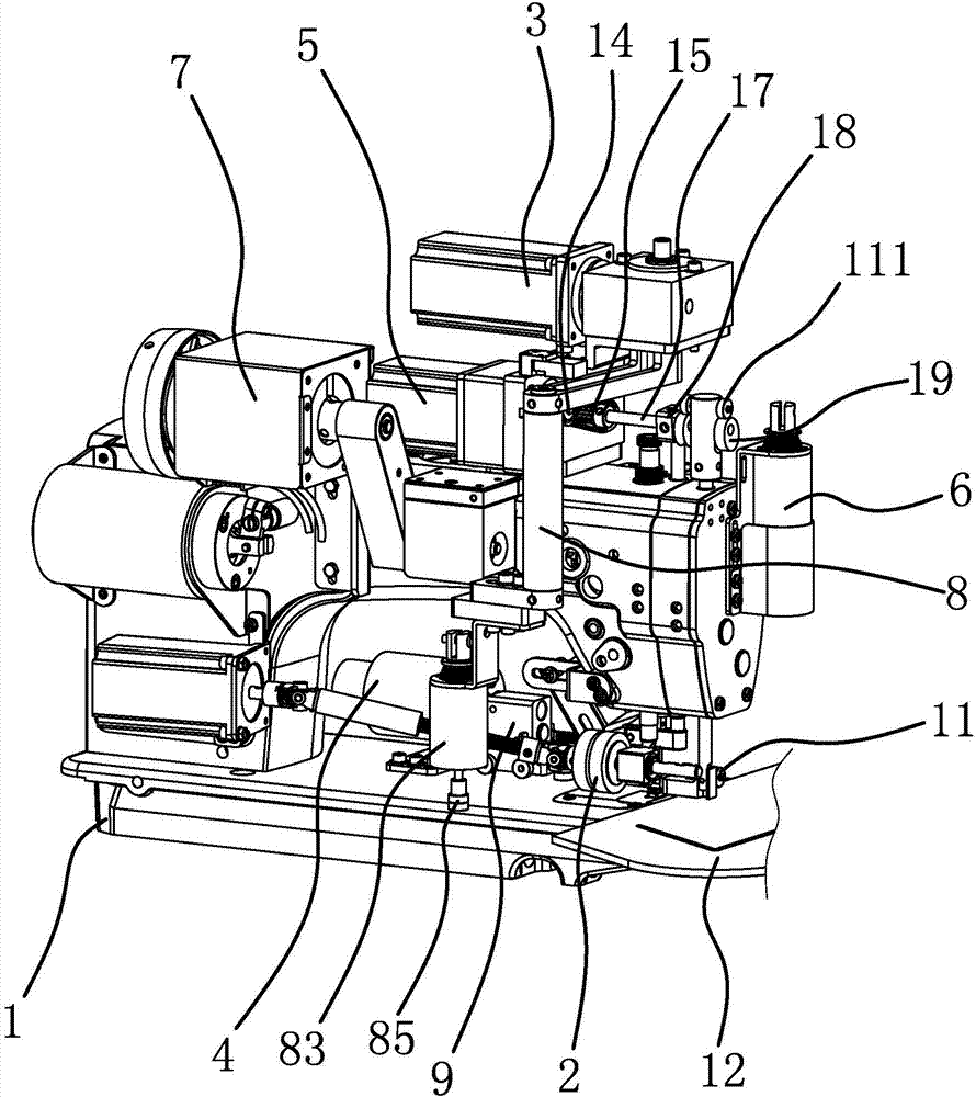
[0035] like figure 1 , figure 2 As shown, the cutter template sewing machine includes a machine head 1, a tug wheel 2, a lifting mechanism, a first driving source 3, a second driving source 4, a third driving source 5, a fourth driving source 6, a fifth driving source 7, A lever mechanism 8, an abutment mechanism 9, a cutter mechanism 10 and an outer presser foot mechanism 11.
[0036] The tugboat 2 is located under the head of the machine head 1, and the lifting and pressing mechanism is arranged in the machine head 1. The lifting and pressing mechanism is connected with the tugboat 2. The lifting and pressing mechanism can make the tugboat 2 move down to press the template 12, and also can make the tugboat 2 move up. Leaving the formwork 12, the lifting and pressing mechanism is a prior art, and will not be described in detail. In this embodiment, the first driving source 3, the third driving source 5 and the fifth driving source 7 are all stepping motors, the second driv...
Embodiment 2
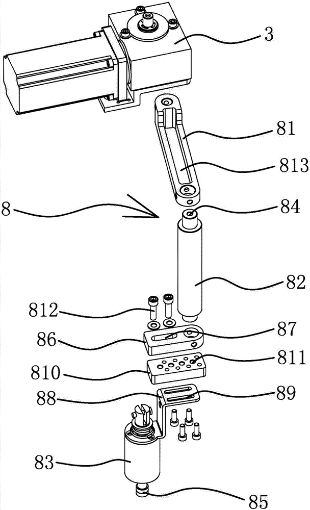
[0044] The structure and principle of this embodiment are basically the same as that of Embodiment 1, the difference is that in this embodiment, the lever mechanism 8 includes a connecting rod 81, a connecting shaft 82 and a sixth driving source 83, and one end of the connecting rod 81 is connected to the sixth driving source 83. A driving source 3 is connected, the other end of the connecting rod 81 is connected with the top of the connecting shaft 82, the connecting rod 81 and the connecting shaft 82 are arranged at right angles, the bottom end of the connecting shaft 82 is connected with the sixth driving source 83, the sixth driving source The output shaft of 83 is arranged downward, and the first driving source 3 can drive the sixth driving source 83 to rotate through the connecting rod 81 and the connecting shaft 82 .
Embodiment 3
[0046] The structure and principle of this embodiment are basically the same as those of Embodiment 1, except that in this embodiment, the included angle between the first driving part 921 and the second driving part 923 is an obtuse angle.
PUM
 Abstract
Description
Claims
Application Information
 - R&D
- Intellectual Property
- Life Sciences
- Materials
- Tech Scout
- Unparalleled Data Quality
- Higher Quality Content
- 60% Fewer Hallucinations
Browse by: Latest US Patents, China's latest patents, Technical Efficacy Thesaurus, Application Domain, Technology Topic, Popular Technical Reports.
© 2025 PatSnap. All rights reserved.Legal|Privacy policy|Modern Slavery Act Transparency Statement|Sitemap|About US| Contact US: help@patsnap.com


