Three-dimensional metal energy dissipation damper

A damper, three-dimensional technology, applied in the direction of building components, building types, earthquake resistance, etc., can solve the problems of three-dimensional vibration damper bulky, lack of practical engineering application, difficult to promote and use, etc., to achieve strong designability and simple structure , cheap effect

Active Publication Date: 2017-11-07
TIANJIN UNIV
View PDF3 Cites 11 Cited by
  • Summary
  • Abstract
  • Description
  • Claims
  • Application Information

AI Technical Summary

Problems solved by technology

[0005] In terms of three-dimensional vibration reduction and energy consumption, there have been related researches in China on the use of rigid masses, elastic layers, springs, and viscoelastic damping units to achieve three-dimensional vibration reduction and energy consumption. The structure makes the three-dimensional vibration damper bulky, inconvenient to install, and expensive. It is mainly used in large-scale industrial facilities for vibration reduction and energy consumption, and it is difficult to promote and use in the field of engineering structures.
At present, the research on three-dimensional dampers is still in the theoretical and experimental stage, and lacks practical engineering applications.

Method used


Image

  • Three-dimensional metal energy dissipation damper
  • Three-dimensional metal energy dissipation damper
  • Three-dimensional metal energy dissipation damper

Examples


Embodiment Construction

[0037] The embodiments of the present invention will be described in detail below in conjunction with the accompanying drawings, so that the advantages and features of the present invention can be more easily understood by those skilled in the art.

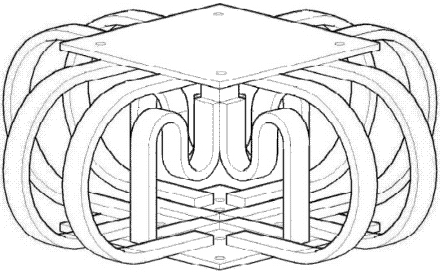
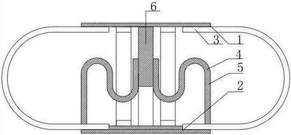
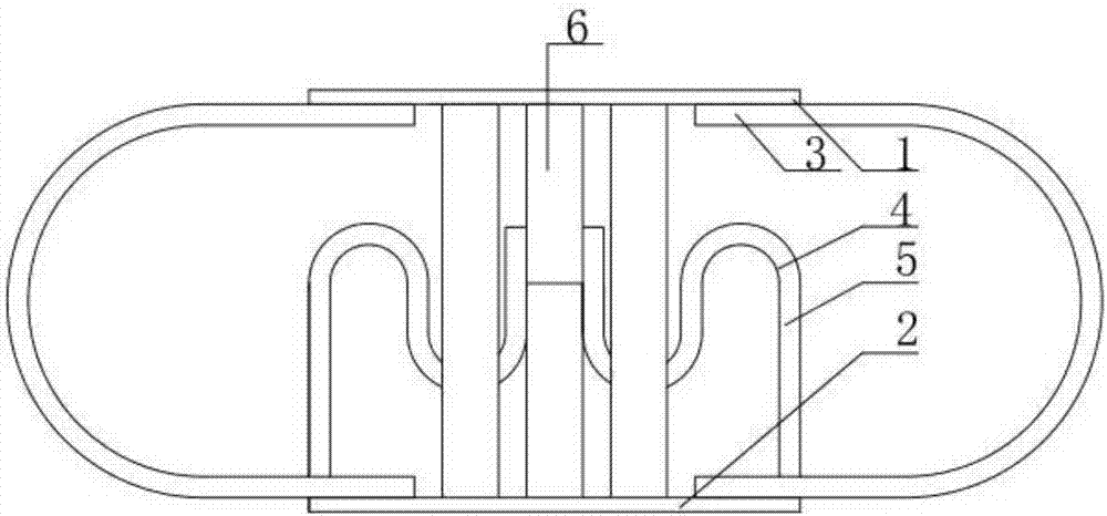
[0038] Such as figure 1 , 3 As shown, a three-dimensional metal energy dissipation damper includes an upper connecting plate 1 , a lower connecting plate 2 , U-shaped steel 3 and S-shaped steel 4 , lateral connecting support columns 5 and central rectangular connecting columns 6 . figure 2 As shown in the sectional view, the energy-dissipating elements mainly include the outer U-shaped steel 3 and the inner S-shaped steel 4. The two straight sections of the U-shaped steel 3 are firmly connected with the upper connecting plate 1 and the lower connecting plate 2 respectively to form a whole. The connection method here can be bolted. Connection or welding, the connection method in this example is welding; the outer surface of the s...


PUM


Abstract

The invention relates to a three-dimensional metal energy dissipation damper. The three-dimensional metal energy dissipation damper comprises an upper connecting plate, a lower connecting plate, U-shaped steel, S-shaped steel, a lateral connecting support column and a central rectangular connecting column. Two flat and straight sections of the U-shaped steel are correspondingly connected with the upper connecting plate and the lower connecting plate to form a whole. The upper end of the central rectangular connecting column is fixedly connected with the upper connecting plate, and the lower end of the central rectangular connecting column is hanging. The outer side surface of a flat and straight section of one end of the S-shaped steel is fixedly connected with the outer side surface of the central rectangular connecting column. The other end of the S-shaped steel and the lateral connecting support column are integrated. The low end of the lateral connecting support column is fixedly connected with the lower connecting plate. The S-shaped steel is symmetrically arranged at the periphery of the central rectangular connecting column. According to the three-dimensional metal energy dissipation damper, the U-shaped steel and the S-shaped steel of special shapes are used as energy dissipation elements, when the upper ends and the lower ends of the U-shaped steel and the S-shaped steel are exerted by shear force and bending moment action, by adopting bending deformation and torsional deformation generated by the U-shaped steel and the S-shaped steel, large deformation is obtained within the limited height, a hysteretic curve is full, the energy dissipation capacity is high, steel fracture is avoided effectively, and the seismic performance of a building structure is improved effectively.

Description

technical field [0001] The invention belongs to the technical field of vibration reduction of civil engineering structures, and in particular relates to a novel three-dimensional metal energy-dissipating damper, which is suitable for vibration reduction of industrial and civil buildings, bridges, water conservancy and important equipment and other projects. Background technique [0002] my country is located in the affected areas of two strong earthquake-prone areas, the circum-Pacific seismic belt and the Eurasian seismic belt, and is a country with frequent earthquakes. How to improve the seismic performance of buildings, bridges, water conservancy, etc. is a problem that engineering design attaches great importance to. In the field of anti-seismic technology of building engineering structures, the easier and more effective vibration reduction method is to add dampers to the structure. At present, the common types of dampers at home and abroad mainly include viscous dampe...

Claims


Application Information

Patent Timeline
Patent Type & Authority Applications(China)
IPC IPC(8): E04H9/02E04B1/98
CPCE04H9/021
Inventor 石运东陈昱坤李忠献丁阳张蒙蒙
Owner TIANJIN UNIV
Why Eureka
Try Eureka