Rapid steam blowing method and device for gas inlet pipeline of turbine

A technology for air intake pipes and steam turbines, applied to safety devices, mechanical equipment, engine components, etc., can solve the problems of cumbersome disassembly and assembly of steam purging detection parts, high production costs, complex structures, etc., and achieve fast and convenient steam purging, Easy to make, low-cost effects

Active Publication Date: 2017-11-07
HUDONG HEAVY MACHINERY
View PDF4 Cites 2 Cited by
  • Summary
  • Abstract
  • Description
  • Claims
  • Application Information

AI Technical Summary

Problems solved by technology

This traditional method is very inconvenient because it involves the disassembly and assembly of multiple pipes; in addition, in order to check and judge whether the purging effect is good, a steam purging detection component needs to be installed at the outlet of the steam purging process pipe
The traditional steam purging detection component is composed of a fixed bracket with a flange, a target plate and a bracket, etc. The structure is relatively complex and the production cost is high. At the same time, due to its specific structure and installation method, in the actual use process, the steam The disassembly and assembly of purge detection components is cumbersome

Method used


Image

  • Rapid steam blowing method and device for gas inlet pipeline of turbine
  • Rapid steam blowing method and device for gas inlet pipeline of turbine
  • Rapid steam blowing method and device for gas inlet pipeline of turbine

Examples


Embodiment Construction

[0026] The following describes the present invention in detail with reference to the drawings and specific embodiments, but the protection scope of the present invention should not be limited by this.

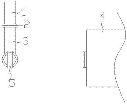
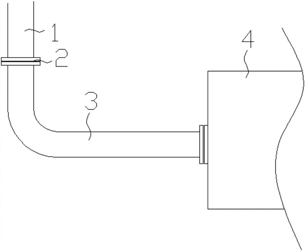
[0027] figure 1 Shown is the fast steam purging method used in the present invention. Before steam purging, the intake pipe 1 is connected to the steam turbine 4 in the original connection mode, see figure 2 .

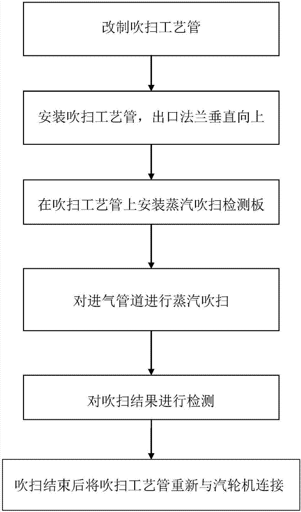
[0028] The fast steam purging method of the steam turbine inlet pipe includes the following specific steps:

[0029] 1) Intercept the last section of steam inlet pipe 1 near the entrance of steam turbine 4 and transform it into purge process pipe 3. The purging process pipe 3 is a right-angle elbow bent at 90°, with flanges fixed at both ends, and a counter flange 2 at one end, which is detachable from the flange at the end of the inlet pipe 1 of the steam turbine 4 by bolts Ground connection, the other end is an outlet flange, which is detachably connected to the steam tur...


PUM


Abstract

The invention provides a rapid steam blowing method for a gas inlet pipeline of a turbine. The rapid steam blowing method for the gas inlet pipeline of the turbine comprises the following steps that (1) a last section of gas inlet pipeline close to an entrance part of the turbine is cut and taken to be remanufactured into a blowing process pipe, the blowing process pipe is a right-angle bend pipe which is bent by 90 degrees, flanges are fixedly arranged at the two ends of the blowing process pipe, the butt-joint flange is fixedly arranged at one end of the blowing process pipe and is connected with a flange at the tail end of the gas inlet pipeline of the turbine, and the exit flange is fixedly arranged at the other end of the blowing process pipe and is connected with the turbine; (2) the position of the blowing process pipe is upwardly rotated by 90 degrees, and the blowing process pipe is installed in a state with the exit flange vertically upward; (3) a target plate serves as a steam blowing detecting plate and is installed on the exit flange of the blowing process pipe; (4) steam is injected into the gas inlet pipeline for blowing; (5) the steam blowing detecting plate is disassembled after each time of blowing and a blowing result is detected until a detecting result meets the requirement; and (6) after blowing for all is finished, the connecting direction of the blowing process pipe is changed and the blowing process pipe is re-connected with the turbine. The rapid steam blowing method for the gas inlet pipeline of the turbine has the advantages that steam blowing is rapid and convenient, working efficiency is high, and cost is low.

Description

Technical field [0001] The invention relates to a manufacturing process of a steam turbine, in particular to a method and a device for rapid steam purging of an intake pipe of a steam turbine, and belongs to the technical field of power equipment manufacturing. Background technique [0002] The steam turbine must have high temperature and high pressure steam input during the normal operation of the steam turbine, and the boiler system that provides high temperature and high pressure steam must rely on the steam pipeline connected between it and the steam turbine for steam transmission. However, during the production, welding and installation of the steam pipeline, not only dirt will enter the pipeline, but also metal particles, metal oxides, welding slag and other impurities will adhere to the inner wall of the pipeline. Although the quick-closing valve of the steam turbine is equipped with a steam filter, after the turbine is put into operation, solid impurities smaller than the...

Claims


Application Information

Patent Timeline
Patent Type & Authority Applications(China)
IPC IPC(8): F01D25/00F01D21/00
CPCF01D21/003F01D25/32
Inventor 冯亮杨凯波张瑾
Owner HUDONG HEAVY MACHINERY
Why Eureka
Try Eureka