
Control method and system for electronic supercharger of vehicle and vehicle

A technology of electronic supercharger and control method, applied in machine/engine, engine components, internal combustion piston engine, etc., can solve problems such as emission deterioration, catalyst blockage, and acceleration performance impact.

Active Publication Date: 2017-11-07
GREAT WALL MOTOR CO LTD
View PDF5 Cites 5 Cited by
  • Summary
  • Abstract
  • Description
  • Claims
  • Application Information

AI Technical Summary

Problems solved by technology

But this requires a process, for example: when the vehicle is accelerating rapidly, the exhaust energy of the engine in the initial stage of rapid acceleration is not enough in several working cycles, and it cannot effectively drive the turbocharger to reach the expected speed, resulting in acceleration hysteresis and affecting Acceleration performance. In addition, when the engine accelerates rapidly, the required boost pressure increases instantaneously. When only the turbocharger is used, the wastegate valve needs to be suffocated as much as possible, so that the boost pressure increases rapidly, which may easily cause the wastegate valve to suffocate. Dead, the exhaust back pressure of the engine increases rapidly, resulting in a rapid increase in fuel consumption, and due to the rapid increase in exhaust back pressure, the combustion in the current few cycles is unstable, and there is a risk of misfire, so there may be deterioration of emissions and blockage of the catalytic converter

Method used


Image

  • Control method and system for electronic supercharger of vehicle and vehicle
  • Control method and system for electronic supercharger of vehicle and vehicle
  • Control method and system for electronic supercharger of vehicle and vehicle

Examples


Embodiment Construction

[0030] It should be noted that, in the case of no conflict, the embodiments of the present invention and the features in the embodiments can be combined with each other.

[0031] The present invention will be described in detail below with reference to the accompanying drawings and examples.

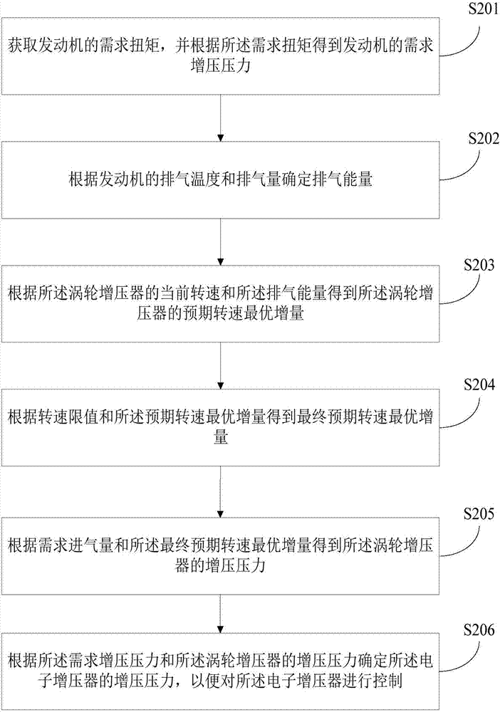
[0032] figure 2 is a flow chart of a control method for an electronic supercharger according to an embodiment of the present invention.

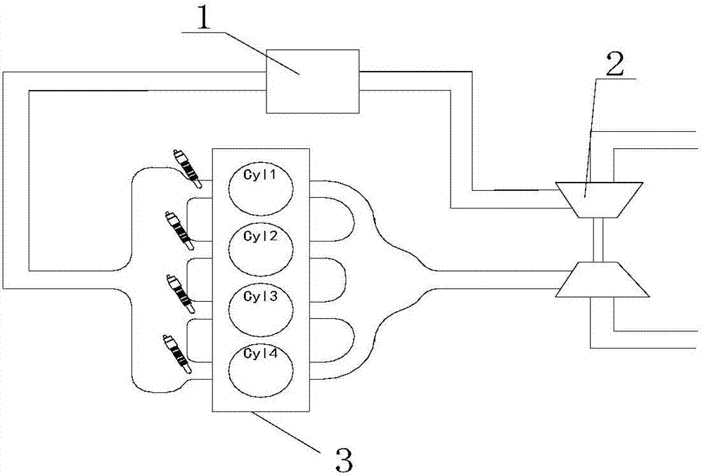
[0033] Before describing the control method of the electronic supercharger of the vehicle according to the embodiment of the present invention, the vehicle is firstly described, the vehicle includes an engine system, and the engine system includes a description, such as figure 1 As shown, the engine system includes an electronic supercharger 1, a turbocharger 2 and an engine 3, wherein the exhaust part of the engine 3 is connected with the turbocharger 2, and the electronic supercharger 1 is connected with the intake part of the engine 3 , In additi...


PUM


Abstract

The invention provides a control method and system for an electronic supercharger of a vehicle and the vehicle. The control method comprises the steps of acquiring needed torque of an engine and obtaining needed supercharging pressure of the engine according to the needed torque; determining exhaust energy according to the exhaust gas temperature and exhaust volume of the engine; obtaining the optimal increment of an expected rotating speed of a turbosuperchager according to the current rotating speed and the exhaust energy of the turbosuperchager; obtaining the optimal increment of a final expected rotating speed according to a rotating speed limiting value and the optimal increment of the expected rotating speed; obtaining supercharging pressure of the turbosuperchager according to needed air inflow and the optimal increment of the final expected rotating speed; and determining supercharging pressure of the electronic supercharger according to needed supercharging pressure and the supercharging pressure of the turbosuperchager so that the electronic supercharger can be controlled. The method can effectively improve the acceleration performance of the vehicle, and has the advantages of energy conservation and emission reduction.

Description

technical field [0001] The invention relates to the technical field of automobiles, in particular to a control method and system for an electronic supercharger of a vehicle, and a vehicle. Background technique [0002] At present, the engine of the vehicle is supercharged by means of a turbocharger, which can improve the acceleration performance of the vehicle to a certain extent. However, when the vehicle is accelerating, the turbocharger needs to use the high-temperature and high-pressure exhaust gas from the engine to drive the turbocharger. Turbo, which in turn supercharges the engine. But this requires a process, for example: when the vehicle is accelerating rapidly, the exhaust energy of the engine in the initial stage of rapid acceleration is not enough in several working cycles, and it cannot effectively drive the turbocharger to reach the expected speed, resulting in acceleration hysteresis and affecting Acceleration performance. In addition, when the engine accele...

Claims


Application Information

Patent Timeline
Patent Type & Authority Applications(China)
IPC IPC(8): F02B37/12F02B37/14F02B39/10F02B37/20
CPCF02B37/12F02B37/14F02B37/20F02B39/10Y02T10/12
Inventor 崔亚彬赵伟博王帅
Owner GREAT WALL MOTOR CO LTD
Learn More