Split electromagnetic coupling

A coupling and split-type technology, which is applied in the direction of magnetic drive clutches, clutches, and non-mechanical drive clutches, etc., to achieve the effects of reducing the requirements for coaxial shafts, reducing the number, and facilitating operation

Active Publication Date: 2017-11-07
LIAONING TECHNICAL UNIVERSITY
View PDF4 Cites 1 Cited by
  • Summary
  • Abstract
  • Description
  • Claims
  • Application Information

AI Technical Summary

Problems solved by technology

In view of the fact that the existing coupling does not have the function of multi-load and time-division driving, the present invention designs a split type electromagnetic coupling, which can meet the functional requirements of mechanical equipment with multi-load and time-division driving, and has two transmission shafts at the same time Axial error compensation capability, which can realize automatic engagement and separation of couplings, is the key technology to realize multi-load driving in different periods

Method used


Image

  • Split electromagnetic coupling
  • Split electromagnetic coupling
  • Split electromagnetic coupling

Examples


Embodiment Construction

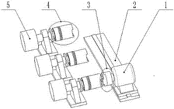
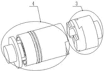
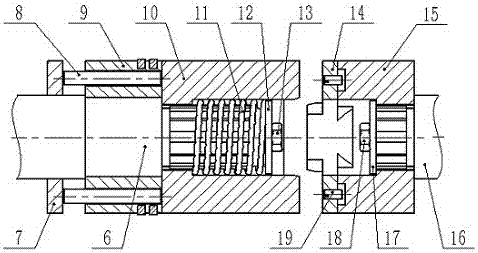
[0013] Examples, see attached Figure 1-6 , a split-type electromagnetic coupling, including a coupling input unit 3 and a coupling output unit 4, taking a power source 1 driving three horizontally arranged loads 5 in different periods as an example, a coupling input unit 3 Installed together with the movable power source 1, the three coupling output units 4 are respectively installed with the loads 5 at three different positions, and the coupling input unit 3 moves along with the power source 1 along the guide rail 2, and can be respectively Engage with any one of the coupling output units 4 arranged in the same direction at three different positions on the same line to drive three loads 5 in different periods; the fixed half-coupling 15 of the coupling input unit 3 Slidingly connected with the slider 14, the coupling output unit 4 is provided with an engaging device and a reset device, and the engaging device can push the movable half-coupling 10 outward along the axial dire...


PUM


Abstract

The invention discloses a split electromagnetic coupling. The split electromagnetic coupling comprises a coupling input unit and a coupling output unit, wherein a movable half-coupling of the coupling output unit is capable of being engaged with a slide block of the coupling input unit under the action of an engagement device, movement and power of a transmission shaft II are transferred to a transmission shaft I, a return device is capable of returning the movable half-coupling, and the transmission shaft I and the transmission shaft II are disengaged, so that the coupling input unit is capable of moving relative to the radial direction of the coupling output unit; and the slide block of the coupling input unit is capable of moving in the radial direction of the movable half-coupling and a fixed half-coupling during a transmission process, so that a coaxiality error of the transmission shaft I and the transmission shaft II is compensated. The split electromagnetic coupling is capable of meeting the functional need of mechanical equipment with a multi-load time-sharing driver, has capacity of compensating the coaxiality error of the transmission shafts, and is easy to realize automatic engagement and disengagement through adopting a working manner of realizing engagement through electromagnetic drive and realizing disengagement through spring return.

Description

technical field [0001] The invention belongs to the field of shaft coupling design, in particular to a split type electromagnetic shaft coupling. Background technique [0002] Couplings are used to connect two transmission shafts to transmit motion and power. Existing couplings are generally used for the connection of two transmission shafts with fixed positions and arranged coaxially. The coaxiality of the two transmission shafts is highly required. , Some couplings have a certain ability to compensate the coaxiality error of the two transmission shafts, but they cannot realize the connection of one transmission shaft with other transmission shafts in different periods through the radial movement position. At present, some equipment has multiple loads, but multiple loads do not work at the same time but work in different periods. Only one load can work at the same time, such as lifting and moving three-dimensional garages. The functional requirements of a load. In view of...

Claims


Application Information

Patent Timeline
Patent Type & Authority Applications(China)
IPC IPC(8): F16D27/09F16D27/14
Inventor 魏永乐晁彩霞于宁田立勇张圣孝李文华
Owner LIAONING TECHNICAL UNIVERSITY
Why Eureka
Try Eureka