Electric-propulsion-field microthrust transient measurement system based on dynamic photoelastic method

A dynamic photoelasticity, measuring system technology, applied in force/torque/work measuring instruments, measuring force, measuring devices, etc., can solve the electromagnetic interference of thrusters, difficult to measure transient thrust, and unable to measure the magnitude of transient thrust of thrusters value and other problems to achieve the effect of reducing mechanical vibration and solving zero drift

Active Publication Date: 2017-11-07
NAT UNIV OF DEFENSE TECH
View PDF6 Cites 14 Cited by
  • Summary
  • Abstract
  • Description
  • Claims
  • Application Information

AI Technical Summary

Problems solved by technology

[0007] The technical problem to be solved by the present invention is that for the thrust that is constantly changing with time generated by the micro thruster, traditional thrust measurement methods such as torsion pendulum and electromagnetic balance cannot measure the instantaneous thrust value of the thruster and the measurement process of the piezoelectric sensor In view of the shortcoming that the thruster is susceptible to electromagnetic interference, a transient thrust measurement system that can measure the thruster's transient thrust and record the entire process of the thruster's thrust change is proposed
The present invention applies the dynamic photoelastic method to the measurement field of the thruster's transient thrust. On the one hand, it has the advantages of simple structure, easy operation and high reliability. The most important thing is to solve the problem that the traditional thrust measurement method is difficult to measure the transient thrust. method

Method used


Image

  • Electric-propulsion-field microthrust transient measurement system based on dynamic photoelastic method
  • Electric-propulsion-field microthrust transient measurement system based on dynamic photoelastic method
  • Electric-propulsion-field microthrust transient measurement system based on dynamic photoelastic method

Examples


Embodiment Construction

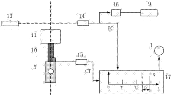
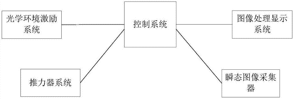
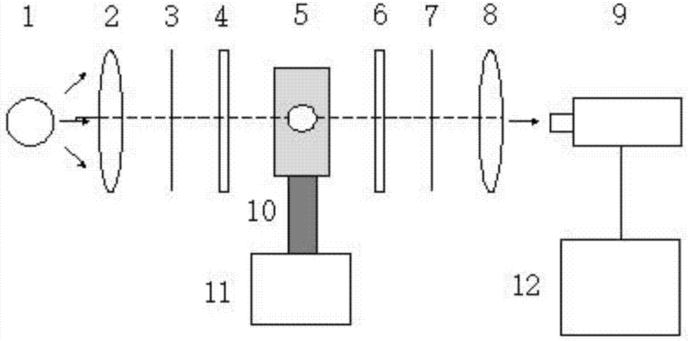
[0035] According to the thrust characteristics of electric propulsion, the present invention is based on the dynamic photoelasticity method and constructs an optical path system with optical elastic elements as the core, and displays the magnitude and change of the instantaneous force by measuring the real-time change of the optical fringe image when it is stressed. The system includes a laser, an optical elastic element, a high-speed transient image collector and necessary image processing techniques. The invention is mainly used for collecting the transient thrust constantly changing with time generated by the pulse type propulsion system. Based on the stress-optical law, the system uses photoelastic special materials and high-speed photography devices to visualize the thrust generated by the thruster, especially to record the change process of the thrust, which is convenient for studying the change mechanism of the thrust of the electric propulsion thruster.

[0036] This s...


PUM


Abstract

The invention relates to an electric-propulsion-field microthrust transient measurement system based on a dynamic photoelastic method. In the invention, according to a thrust characteristic of electric propulsion, based on the dynamic photoelastic method, an optical elastic component is taken as a core so as to construct an optical path system; and through measuring real-time changes of an optical stripe image under a stress, instantaneous stress size and change conditions are displayed. The system comprises a laser, the optical elastic component, a high-speed transient image collector and a necessary image processing technology. The system is mainly used for collecting transient thrusts which are continuously changed along with time and are generated by a pulse-type propulsion system. The system is based on a stress-optical law. A photoelastic special material and a high-speed photography device are used to visualize the thrusts generated by a thruster, and a change process of the thrusts is especially recorded so as to research a change mechanism of the thrusts of an electric propulsion thruster.

Description

technical field [0001] The invention relates to a micro-thrust measurement system, in particular to a real-time measurement system for the micro-thrust in the field of electric propulsion. Background technique [0002] At present, the domestic high-precision measurement of micro-thrust and micro-impulse of electric propulsion thrusters is more commonly based on thrust measurement systems such as simple pendulum, inverted pendulum, and torsion pendulum. Among them, when the electromagnetic balance based on the inverted pendulum principle measures the impulse, there is a serious zero point drift, and the unstable balance position of the electromagnetic balance also leads to poor measurement accuracy. Therefore, it can generally only be used for qualitative or semi-quantitative analysis. [0003] Relatively speaking, the use of torsion pendulum to measure thrust or impulse has high accuracy and sensitivity. The history of torsion pendulum can be traced back to the torsion balan...

Claims


Application Information

Patent Timeline
Patent Type & Authority Applications(China)
IPC IPC(8): G01L1/24G01L5/00
CPCG01L1/241G01L5/0038
Inventor 吴建军何振欧阳张宇李健何兆福
Owner NAT UNIV OF DEFENSE TECH
Why Eureka
Try Eureka