Microscope laboratory system

A laboratory and microscope technology, applied in the field of microscope laboratory systems, can solve the problems of low image purity, inability to obtain accurate image data, and inability to meet the needs of measurement

Inactive Publication Date: 2017-11-07
李昊天
View PDF7 Cites 2 Cited by
  • Summary
  • Abstract
  • Description
  • Claims
  • Application Information

AI Technical Summary

Problems solved by technology

[0010] To sum up, the problems existing in the existing technology are: the throughput of the measurement data of the existing microscope system is small, w

Method used


Image

  • Microscope laboratory system
  • Microscope laboratory system
  • Microscope laboratory system

Examples


Embodiment Construction

[0127] In order to make the object, technical solution and advantages of the present invention more clear, the present invention will be further described in detail below in conjunction with the examples. It should be understood that the specific embodiments described here are only used to explain the present invention, not to limit the present invention.

[0128] The application principle of the present invention will be described in detail below in conjunction with the accompanying drawings.

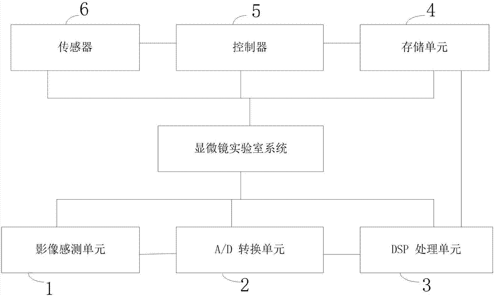
[0129] Such as figure 1 As shown, the microscope laboratory system provided by the embodiment of the present invention includes:

[0130] The light reaches the image sensing unit 1 through the lens, and the image sensing unit is used to convert the optical signal into an electrical signal, and transmit the electrical signal to the A / D conversion unit;

[0131] The A / D conversion unit 2 is used to convert the electrical signal transmitted by the image sensing unit into a digital signa...


PUM


Abstract

The present invention belongs to the detection equipment technology field, and discloses a microscope laboratory system. The microscope laboratory system comprises an image sensing unit to which the light rays reach via a lens; an A/D conversion unit used for converting an electric signal transmitted by the image sensing unit into a digital signal; a DSP unit used for converting the digital signal transmitted by the A/D conversion unit into a digital image and transmitting to a storage unit; the storage unit used for storing the digital image processed by the DSP unit; a controller used for adjusting the focal length of the lens when the image sensing unit measures; a sensor used for obtaining the information of the image when the image sensing unit measures. According to the present invention, the automatically acquired image can be displayed on a special-purpose display real-timely, thereby improving an intuitional problem; the storage unit image identification solves an image confusion problem in the prior art, and the miscellaneous signals that cannot be something else are filtered, thereby guaranteeing the purification of the image.

Description

technical field [0001] The invention belongs to the technical field of detection equipment, in particular to a microscope laboratory system. Background technique [0002] As related systems related to measuring devices including microscopes, those discussed in PTL1 and PTL2 are provided. In PTL1, after macro-inspection for visually observing scratches and strains on the wafer surface is performed, micro-inspection is performed to finely inspect positions for confirmation of features using a microscope. In a structure for performing such inspection, a macro-inspection unit capable of rotating / tilting a wafer is provided between the carrier and the micro-inspection unit. Although wafers are often inspected using separate devices (ie, a macro-inspection device and a micro-inspection device), such a structure for performing such inspections enables simplification of the inspection process. [0003] In PTL2, a structure includes an objective lens and a focus setting objective l...

Claims


Application Information

Patent Timeline
IPC IPC(8): G05B13/04G05B11/42G05B19/042
CPCG05B11/42G05B13/042G05B13/048G05B19/042G05B19/0423G05B2219/21137
Inventor 李昊天
Owner 李昊天
Why Eureka
Try Eureka