End-milling plane forming surface three-dimensional modeling method

A surface forming and three-dimensional modeling technology, which is applied in 3D modeling, image data processing, instruments, etc., can solve the problems of surface roughness and surface shape that cannot be formed, and achieve good intuitiveness, high precision and high efficiency Effect

Inactive Publication Date: 2018-06-01
XIAMEN UNIV OF TECH
View PDF8 Cites 10 Cited by
  • Summary
  • Abstract
  • Description
  • Claims
  • Application Information

AI Technical Summary

Problems solved by technology

[0006] The present invention aims to provide a three-dimensional modeling method for the plane forming surface of end milling, so as to solve the problem that the surface roughness value Ra and the shape of the forming surface cannot be obtained in the surface prediction of the existing end milling process

Method used


Image

  • End-milling plane forming surface three-dimensional modeling method
  • End-milling plane forming surface three-dimensional modeling method
  • End-milling plane forming surface three-dimensional modeling method

Examples


Embodiment Construction

[0031] To further illustrate the various embodiments, the present invention is provided with accompanying drawings. These drawings are a part of the disclosure of the present invention, which are mainly used to illustrate the embodiments, and can be combined with related descriptions in the specification to explain the operating principles of the embodiments. With reference to these contents, those skilled in the art should understand other possible implementations and advantages of the present invention. Components in the figures are not drawn to scale, and similar component symbols are generally used to denote similar components.

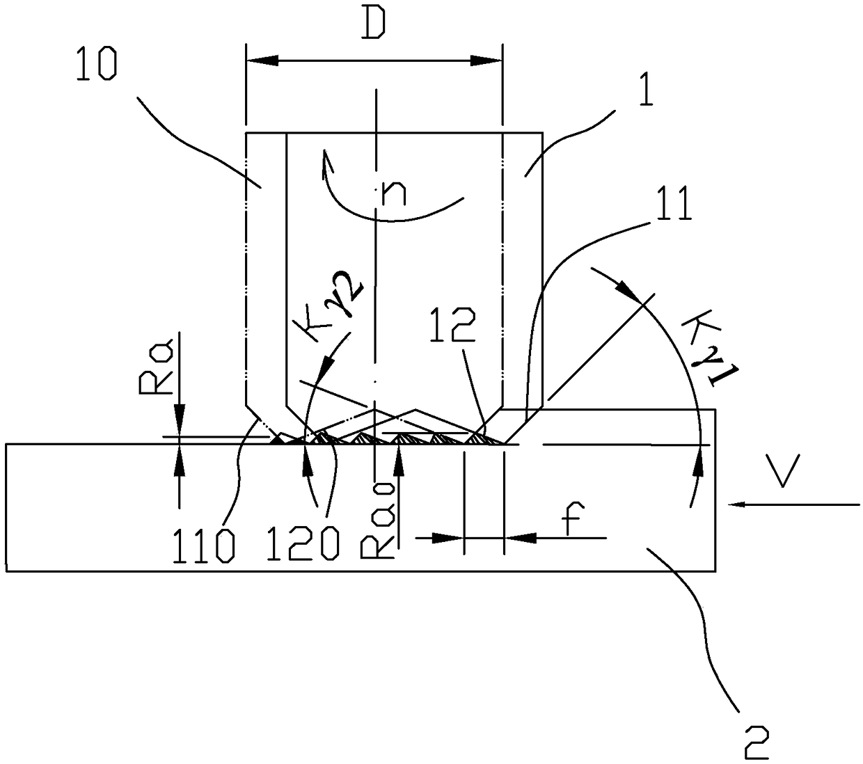
[0032] combine figure 1 As shown, in the prior art, the milling process is simulated by a two-dimensional modeling method, and the formed surface is the surface obtained by end milling the plane. The workpiece 2 is fed at a speed V. Relative to the moving direction of the workpiece 2, the milling cutter 1 rotates at the initial position to form ...


PUM


Abstract

The invention relates to an end-milling plane forming surface three-dimensional modeling method, and the method employs UG software for simulating a milling movement. The method comprises the steps: building a three-dimensional model of one-cycle movement of a main knife edge and an auxiliary knife edge during the plane milling; enabling the three-dimensional model to move in a feeding direction through commands of transformation and copying; obtaining the three-dimensional model on the whole forming surface, and obtaining a sleeking weld reinforcement region as a three-dimensional model of the forming surface. The method also proposes a method for determining the surface roughness Ra. The method for determining the surface roughness Ra comprises the steps: obtaining the maximum coordinates of the main knife edge or main sleeking knife edge of the sleeking weld reinforcement region through the commands of information and point of UG software, and obtaining the surface roughness Ra (mm). The UG three-dimensional modeling method is used for building the three-dimensional model of the forming surface, and the three-dimensional model visually reflects an end-milling plane forming surface, and obtains the surface roughness Ra value at the same time. The visuality is good, and the efficiency and precision are high.

Description

technical field [0001] The invention belongs to the technical field of mechanical processing software simulation analysis, and in particular relates to a three-dimensional modeling method for a plane forming surface processed by end milling. Background technique [0002] At present, in the research of surface roughness prediction in end milling, the theoretical surface roughness prediction method is established based on cutting theory, and the surface roughness value is calculated from a geometric point of view. There are three main calculation methods: [0003] Two-dimensional drawing method: simulate the movement of the end milling plane on the drawing, and draw the two-dimensional schematic diagram of the triangular cross-section of the main cutting edge and auxiliary cutting edge in the moving plane of the centerline of the milling cutter, and the main cutting edge in the trimming relief area Two-dimensional schematic diagram of the double triangular section formed by t...

Claims


Application Information

Patent Timeline
Patent Type & Authority Applications(China)
IPC IPC(8): G06T17/00
CPCG06T17/00
Inventor 刘金武陈阿龙易子超王平
Owner XIAMEN UNIV OF TECH
Why Eureka
Try Eureka