
A bus differential protection method and device using self-synchronization technology
A busbar differential protection and self-synchronization technology, applied in emergency protection circuit devices, electrical components, etc., can solve problems such as increasing construction costs and occupying transmission channel resources, saving construction capital, small busbar distributed capacitance, and strong self-adaptation sexual effect
Patent Information
- Authority / Receiving Office
- CN · China
- Patent Type
- Patents(China)
- Current Assignee / Owner
- Publication Date
- 2018-11-13
Smart Images
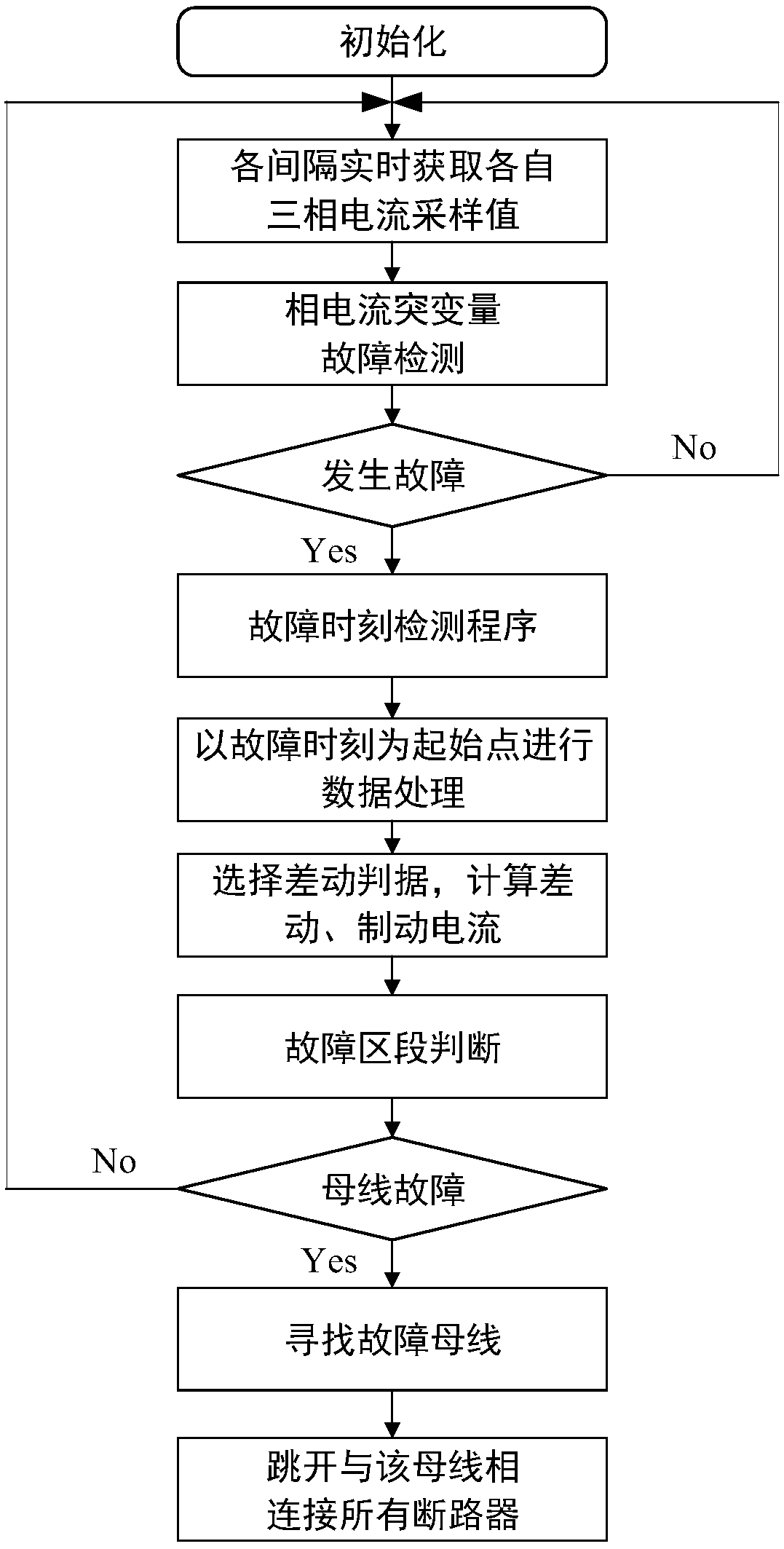
Figure 1 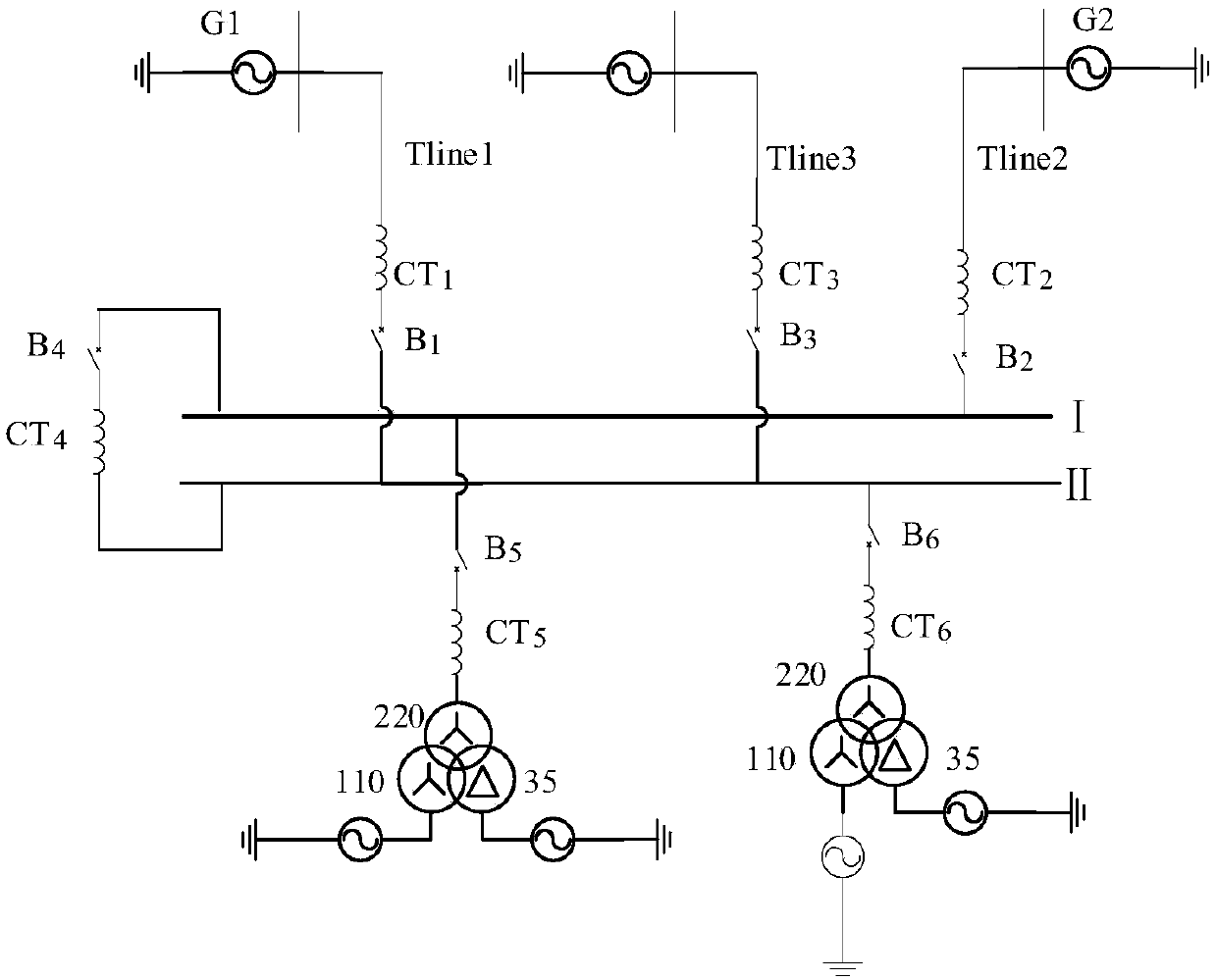
Figure 2 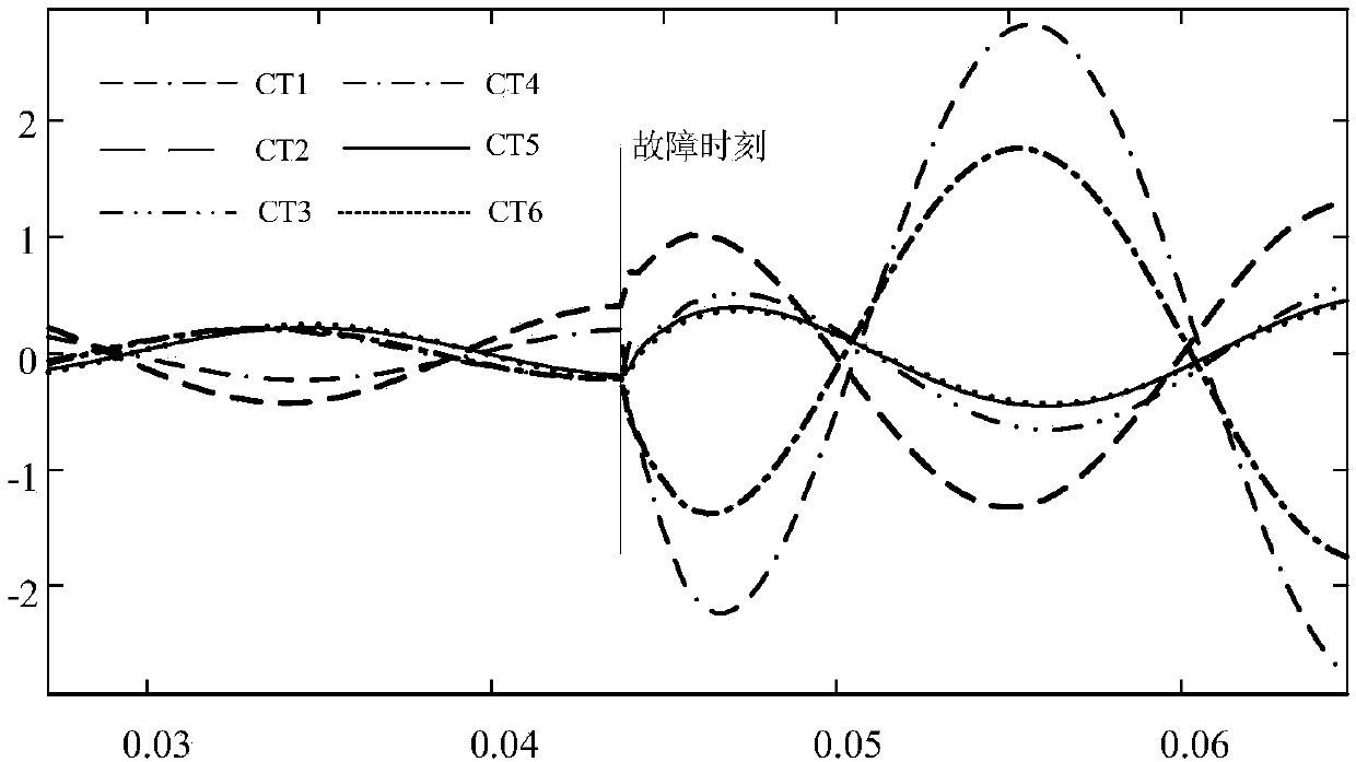
Figure 3
Abstract
Description
technical field
[0001] The invention belongs to the field of relay protection of electric power systems, in particular to a bus differential protection method and device using self-synchronization technology. Background technique
[0002] With the continuous expansion of the grid structure and scale of the national power system, more and more smart substations have been completed or are under construction. As the main structure of the substation, the busbar undertakes the important functions of collecting, distributing and transmitting electric energy. There are many electrical equipment connected to the busbar, and the structure of the incoming and outgoing lines is complex. If the busbar fails, it will affect the safety of the system and cause huge economic losses. Bus safety plays an important role in the stable operation of substations and power systems.
[0003] The bus adopts a fully selective current differential protection as the main protection. Busbar protection...
Examples
Embodiment 1
[0066] combine figure 1 The fault processing flow chart shown in the figure shows the implementation process of the bus differential protection method using self-synchronization technology by taking the A-phase ground fault of the II bus as an example:
[0067] Step 1: collect the three-phase instantaneous current at each bay protection installation place connected to the busbar, and calculate the sudden change of the three-phase instantaneous phase current at each bay in real time. In this step, according to domestic smart substation standards, the sampling frequency is 4 kHz, the number of sampling points per cycle is N=80, and the sampling time interval is 0.25 ms.
[0068] In the specific implementation process, the current transformers CT1, CT2, CT3, CT4, CT5, and CT6 are used to measure the instantaneous current of each interval three-phase in real time, the sampling frequency is 4kHz, and 80 points are collected per cycle; Current sudden change Δi φ .
[0069] In add...
Embodiment 2
[0105] A phase-to-ground fault occurs on the line Tline3, and the fault handling process is the same as that in Embodiment 1. Table 2 shows the estimated fault times of each interval.
[0106] Table 2 The fault time obtained for each interval when the line is faulty
[0107]
[0108]
[0109] When a phase-A ground fault occurs on line Tline3, the protection action characteristics of the large bus difference, Ⅰ bus small difference, and Ⅱ bus small difference are as follows: Figure 5(a)-Figure 5(c) shown.
[0110] As shown in Table 1 and Table 2, the fault time calculated for each interval is very close to the actual fault occurrence time, the maximum error is only 0.25ms, and the phase angle error is only 4.5°, which is within the allowable range of differential protection. At a sampling frequency of 4kHz, there is only one sampling point difference from the real fault time, and the synchronization accuracy fully meets the synchronization requirements of differential p...