Colander-type feeding device

A technology of a feeding device and a colander, which is applied in the field of cooking machines, can solve problems such as low degree of automation, and achieve the effects of improving the automation rate, ensuring the taste and quality, and meeting the requirements of necessary moisture and oil content.

Active Publication Date: 2017-11-10
徐州大自然食品有限公司
View PDF8 Cites 1 Cited by
  • Summary
  • Abstract
  • Description
  • Claims
  • Application Information

AI Technical Summary

Problems solved by technology

However, the feeding unit of the existing cooking machine is not equipped with a water or oil immersion device, and can only be completed by manual sprinkling, which has a low degree of automation and needs to be improved.

Method used


Image

  • Colander-type feeding device
  • Colander-type feeding device
  • Colander-type feeding device

Examples


Embodiment 1

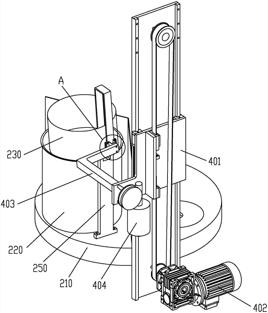
[0021] Example 1, see figure 1 , figure 2 , image 3 and Figure 4 , a colander type feeding device, comprising a colander 230 and a colander driving device, the colander 230 is placed in the material preparation cylinder 220, the material preparation cylinder 220 is arranged on the material preparation turntable 210, and the colander 230 forms a structure that can only be taken out from above through the colander positioning structure; The colander driving device is connected to the colander 230 through an elastic force coupling structure, and the colander driving device has a structure that lifts the colander 230 from the opening of the material storage tank 220 and turns over at least 90 degrees.

[0022] Wherein, the colander driving device includes a sliding table 401 set on the frame through a pair of guide rails. The sliding table 401 is driven to move by a sliding table lifting motor 402 through a synchronous belt transmission structure. The sliding table lifting mo...

Embodiment 2

[0023] Example 2, see Figure 5 , the spring clamp is composed of claws 407, and the two claws 407 are respectively fixedly connected to two claw arms 408, and the two claw arms 408 are hinged by hinge shafts 409, and there is a The loading spring 410 , the elastic force of the loading spring 410 drives the two claws 407 outward; the elastic clamp is connected with the connecting arm 403 through the transfer shaft 409 .

[0024] The rest of the structure of this embodiment is the same as that of Embodiment 1, and will not be repeated here.

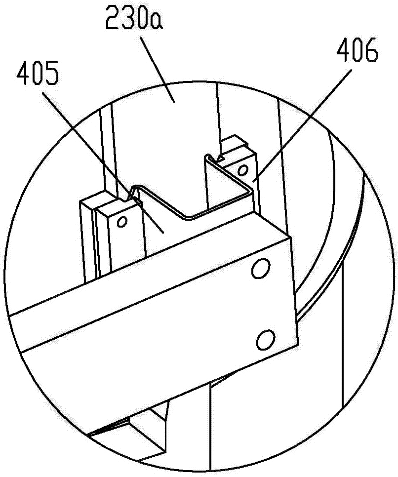
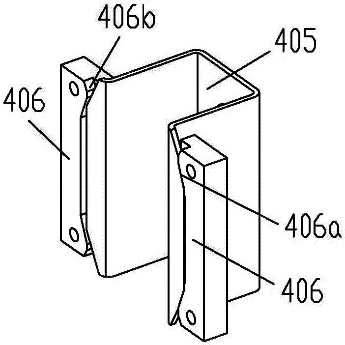
[0025]The colander driving device and the colander 230 in the foregoing embodiments are also connected through a magnetic coupling structure. The magnetic coupling includes two permanent magnets coupled to each other, the two permanent magnets are respectively arranged on the colander handle 230a and the connecting arm 403; when the connecting arm 403 moves to a set position, the connecting arm 403 forms a magnetic force with the colander...


PUM


Abstract

The invention discloses a colander-type feeding device. The colander-type feeding device comprises a colander and a colander driving device. The colander is arranged in a material preparing cylinder, and can be taken out of the upper portion; the colander driving device is connected with the colander through a magnetic force or elastic force coupling structure, comprises a structure which is capable of lifting and taking the colander out of a cylinder opening of the material preparing cylinder and allowing the colander to overturn at least 90 degrees, and comprises a sliding table arranged on a machine frame in a sliding mode through a guiding rail pair, and the sliding table is driven by a sliding-table lifting motor to move through a synchronous belt transmission structure; a connecting arm is rotatably arranged on the sliding table, and is driven by a colander rotating motor to rotate through a worm and gear transmission structure, and the colander driving device is coupled with the colander through the connecting arm. The colander-type feeding device has the advantages that the necessary moisture and oil requirements of dishes can be fully met, and the taste and the quality of the dishes are guaranteed; it is achieved that raw material vegetables in the colander are automatically added into a pot through the colander driving device, and the automation rate of a cooking machine is increased.

Description

technical field [0001] The patent of the present invention relates to a cooking machine, in particular to a colander type feeding device for the cooking machine. Background technique [0002] Large cooking machine or cooking equipment is a kind of kitchen equipment used in Chinese canteens, restaurants, hotels, Chinese fast food restaurants or central kitchens. With the acceleration of people's life rhythm and the increase of labor costs, the original large-scale cooking machine has been difficult to adapt to the development of the market. With the popularization of intelligent technology, at present, intelligent cooking equipment has appeared, which has a high degree of automation, high efficiency, less artificial factors affecting the quality of dishes, good taste and high quality. Therefore, the automatic cooking machine is an ideal equipment to replace manual cooking. Some dishes need to be soaked in water or oil before cooking. However, the feeding unit of the existi...

Claims


Application Information

Patent Timeline
Patent Type & Authority Applications(China)
IPC IPC(8): A47J36/00A47J47/01
CPCA47J36/00A47J47/01
Inventor 谭明刘刚
Owner 徐州大自然食品有限公司
Why Eureka
Try Eureka