
Manipulation device of detector of subjective vision vertical line and subjective vision horizontal line

A technology of control devices and detectors, which is applied in diagnostic recording/measurement, medical science, sensors, etc., can solve the problems of long time consumption, slow adjustment speed, and bulky volume, and achieve low error rate and high efficiency. , time-saving effect

Pending Publication Date: 2017-11-10
SHANGHAI ZEHNIT MEDICAL TECH CO LTD
View PDF7 Cites 0 Cited by
  • Summary
  • Abstract
  • Description
  • Claims
  • Application Information

AI Technical Summary

Problems solved by technology

However, both solutions have the following disadvantages: 1) The volume of the equipment is still huge. Since the dynamic SVV test requires the subject to perform under the condition of dynamic unilateral centrifugal rotation, neither of the two devices can be used for the dynamic SVV test; at the same time, due to the same Because of the reason, the subject cannot be measured in a static position such as supine
2) Both schemes cannot detect the subject's head orientation, and when the subject's head tilts forward, backward or left and right, it will have many effects on the SVV measurement (Dyde et al, 2005), so Neither solution can provide SVV measurement results when the subject is in any non-upright position
Through the investigation in the hospital, it was found that when the subjects, especially the middle-aged and elderly subjects, pressed the button for too long each time, or a single press of the button was normal, but the adjustment speed was very slow, so it often appeared The subject has difficulty adjusting the line segments in his field of vision to what he thinks are vertical, or it takes a long time to do it each time

Method used


Image

  • Manipulation device of detector of subjective vision vertical line and subjective vision horizontal line
  • Manipulation device of detector of subjective vision vertical line and subjective vision horizontal line
  • Manipulation device of detector of subjective vision vertical line and subjective vision horizontal line

Examples


Embodiment Construction

[0017] Such as figure 2 and image 3 As shown, the present invention will be further described below through specific embodiments.

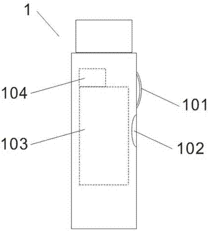
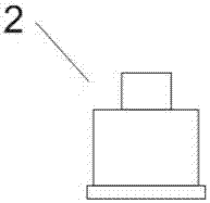
[0018] The control device of the subjective visual vertical line and subjective visual horizontal line detector of the present invention includes a control body 1 and a signal receiver 2 connected to the detector, and the control body 1 is provided with a knob 101 and a confirmation key 102 (preferably The knob 101 and the confirmation key 102 are only one), the control body 1 is provided with a roller encoder 103 and a signal transmitter 104; the knob 101 and the confirmation key 102 are connected to the roller encoder 103, the The signal transmitter 104 is connected to the signal receiver 2 , and the roller encoder 103 is arranged between the signal transmitter 104 and the signal receiver 2 . The knob 101 is rotated clockwise or counterclockwise to control the roller encoder 103, and the roller encoder 103 transmits the control signal to the...


PUM


Abstract

The invention relates to a manipulation device of a detector of a subjective vision vertical line and a subjective vision horizontal line. The device comprises a manipulation body and a signal receiver connected to the detector, wherein a knob and a confirmation key are disposed on the manipulation body, and a roller encoder and a signal emitter are disposed in the manipulation body; and the knob and the confirmation key are connected to the roller encoder, the signal emitter is connected to the signal receiver, and the roller encoder is disposed between the signal emitter and the signal receiver. The manipulation device provided by the invention is used to adjust a deviation position of a straight line appearing in a patient's vision field in an SVV host during inspection of a system of the subjective vision vertical line and subjective vision horizontal line; use is easy, and use error rate is low; time of doctors and patients can be saved greatly; and statistic effectiveness of inspection results can be increased.

Description

technical field [0001] The invention relates to components of a medical equipment detection instrument, in particular to a control device for a subjective visual vertical line and a subjective visual horizontal line detection instrument. Background technique [0002] The subjective visual vertical line (SVV) and subjective visual horizontal line (SVH) test is to detect the angle between the patient's perceived vertical line / perceived horizontal line and the gravity vertical line / gravity horizontal line in an environment without visual reference objects, and the test results are used It is used to evaluate the otolith organ (Otolith organ) function of the subjects, and then serve as the basis for diagnosis of balance system diseases. [0003] According to the Chinese patent document CN201320765676, Wang Pengjun invented a mobile subjective vertical visual static balance inspection instrument; according to the Chinese patent document CN201520127985.4, Han Junliang and others d...

Claims


Application Information

Patent Timeline
IPC IPC(8): A61B5/00
CPCA61B5/4023
Inventor 屈寅弘庄建华于艳山柯玛庭
Owner SHANGHAI ZEHNIT MEDICAL TECH CO LTD
Learn More