
Method for controlling welding path of welding robot

A welding robot and welding path technology, applied in welding equipment, welding accessories, program control manipulators, etc., can solve problems such as poor weld quality and poor welding uniformity, and achieve low cost, high reliability, and simple software design.

Active Publication Date: 2017-11-10
JIANGSU MICFIRST AUTOMATION TECH
View PDF7 Cites 5 Cited by
  • Summary
  • Abstract
  • Description
  • Claims
  • Application Information

AI Technical Summary

Problems solved by technology

[0004] The invention provides a system with simple structure, low cost, simple control mode and high reliability and its welding path control method, which is used to solve the problems of poor welding uniformity and poor quality of welding seam

Method used


Image

  • Method for controlling welding path of welding robot
  • Method for controlling welding path of welding robot
  • Method for controlling welding path of welding robot

Examples


Embodiment Construction

[0023] The invention provides a welding robot system and a welding path control method with simple structure, low cost, simple control mode and high reliability:

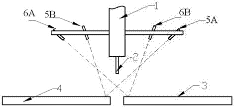
[0024] A welding robot includes a mechanical arm, a cage fixed at the end 1 of the mechanical arm, a welding torch 2 mounted on the end 1 of the mechanical arm, and an error correction system mounted on the cage. According to the instructions of the control system, the mechanical arm Drive the welding torch 2 above the seam and move along a predetermined path to complete the welding of 3 / 4 of the two plates;

[0025] The error correction system includes first and second detection components 5 / 6 and a filter;

[0026] The detection parts 5 / 6 include energy emitters 5A\6A and energy detectors 5B\6B respectively located on one side and the other side of the welding torch 2; and, the energy emitters 5A of the first detection part and the The energy detector 6B is located on the same side of the welding torch 2;

[002...


PUM


Abstract

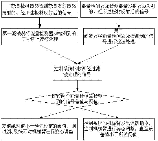
The invention relates to a method for controlling the welding path of a welding robot. A control system detects and adjusts the position and posture of a welding gun in real time, so that the welding gun is always positioned right above a welding seam. Moreover, the control system judges an energy difference value detected by an energy detector according to received information; if the absolute value of the difference value is less than a preset threshold valve, the control system does not adjust the posture of a mechanical arm; if the difference value is greater than or equal to the threshold value, the control system issues a movement command to the mechanical arm and controls the mechanical arm to adjust the posture, until the difference value is less than the threshold value and the welding gun moves to right above the welding seam and is vertical to be plane of a plate.

Description

technical field [0001] A method for controlling a welding path of a welding robot. Background technique [0002] A welding robot is a mechanical device that completes welding operations under the control of an automatic controller. The welding robot has reliable welding quality, high precision, and good environmental adaptability. Therefore, the application of robot welding is becoming more and more extensive and common. [0003] In order for the robot to complete the welding work along the predetermined welding path, the predetermined program must be set in advance. However, due to various errors such as control errors and mechanical errors, there is a certain gap between the actual welding path of the robot and the predetermined welding path. Welding errors; in high-precision welding occasions, through various sensors or control algorithms to minimize welding errors as much as possible. Based on this, aiming at the high cost and complicated control of the existing equipme...

Claims


Application Information

Patent Timeline
Patent Type & Authority Applications(China)
IPC IPC(8): B23K9/12B23K9/127B23K9/32B25J9/16
CPCB23K9/12B23K9/1272B23K9/32B25J9/1664
Inventor 王锐
Owner JIANGSU MICFIRST AUTOMATION TECH
Learn More