Steel plate splicing welding joint bottom-surface ceramic liner lifting device and operation method thereof

A technology of ceramic gaskets and splicing welds, which is applied in auxiliary devices, welding/welding/cutting items, welding equipment, etc. Difficulty of operation and construction cost, improving installation efficiency and avoiding unfavorable factors

Active Publication Date: 2017-11-10
中国人民解放军63926部队
View PDF7 Cites 1 Cited by
  • Summary
  • Abstract
  • Description
  • Claims
  • Application Information

AI Technical Summary

Problems solved by technology

However, in the actual installation process of the ceramic liner at the bottom of the high-altitude panel, there are technical problems such as large workload, low efficiency and high risk of high-altitude operations in setting up auxiliary facilities such as operating platforms

Method used


Image

  • Steel plate splicing welding joint bottom-surface ceramic liner lifting device and operation method thereof
  • Steel plate splicing welding joint bottom-surface ceramic liner lifting device and operation method thereof
  • Steel plate splicing welding joint bottom-surface ceramic liner lifting device and operation method thereof

Examples


Embodiment 1

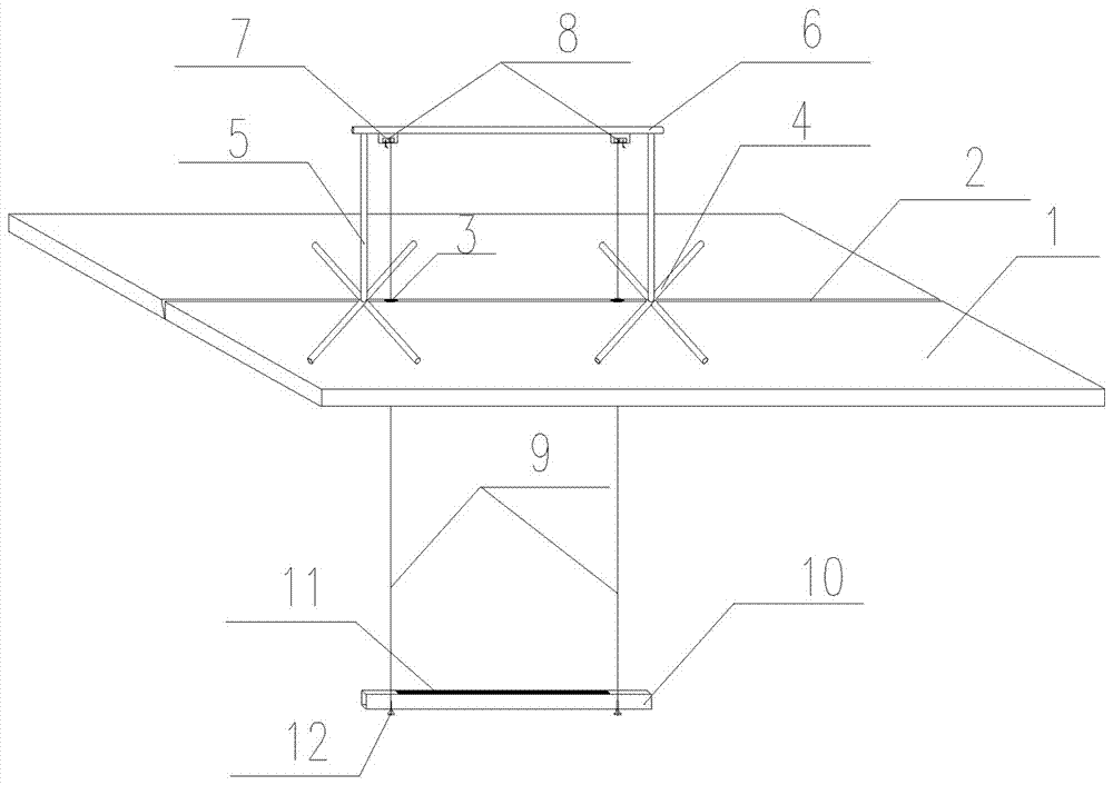
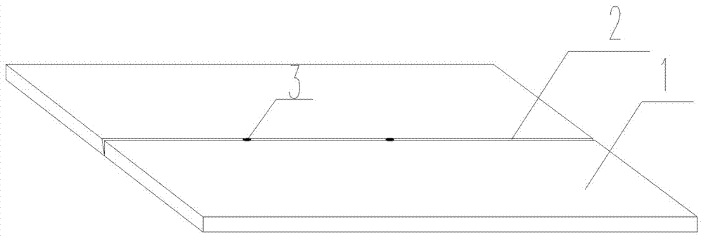
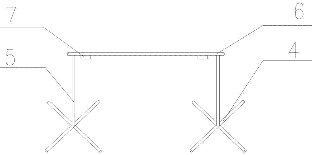
[0029] Such as Figure 1~7 As shown, a ceramic liner lifting device on the bottom surface of the steel plate splicing weld includes a lifting hanger installed on the upper surface of the welded steel plate 1, a lifting device fixedly connected with the lifting hanger and passing through the steel plate weld 2, and a lifting device installed on the lifting device. The pad bracket 10 at the bottom; the lifting hanger includes a crossbar 6 horizontally arranged above the welded steel plate 1, two columns 5 vertically fixedly connected to the two ends of the crossbar 6 and a stable base frame 4 provided at the bottom of the column 5 , the stable base frame 4 is erected on the upper surface of the welded steel plate 1; the lifting device includes two sets of pulley assemblies connected to both ends of the cross bar 6 and steel wire ropes 9 respectively connected to each set of pulley assemblies, and the steel wire ropes 9 pass through The plate hole 3 at the welding seam 2 of the s...

Embodiment 2

[0034] The operation steps of the installation method of the ceramic liner lifting device on the bottom surface of the spliced ​​weld seam of the steel plate in embodiment 1.

[0035] Lift hanger design:

[0036] According to the actual needs of the project, determine the size and other conditions of the lifting hanger to ensure the strength and stability of the hanger;

[0037] Lifting device design:

[0038] According to the maximum lifting height, hoisting weight and other conditions, select the appropriate lifting pulley and wire rope, design and rigidly fix the upper hanger, and the steel wire rope is hinged with the lower fixed beam to ensure reliable connection, and analyze and design weak nodes.

[0039] Operation method:

[0040] Assemble the hoisting hanger, hoisting device and lower liner bracket on site, and after the overall commissioning and operation of the mechanism is complete, the liner will be formally lifted and installed in place.

[0041] First, the br...


PUM


Abstract

The invention discloses a steel plate splicing welding joint bottom-surface ceramic liner lifting device and an operation method thereof. The device comprises a lifting hanging rack, a lifting device body and a liner bracket, wherein the lifting hanging rack is mounted on the upper surface of welded steel plates; the lifting device body is fixedly connected with the lifting hanging rack and penetrates through a steel plate welding joint; the liner bracket is mounted at the bottom of the lifting device body; and the lifting device body comprises pulley blocks each provided with a self-locking device. By means of the method, a liner is lifted to a welding joint plate bottom position to be put in place from the ground (floor) surface through the lifting device body, is fixed through the self-locking devices and then is mounted at the highly-aloft surface steel plate welding joint, so that welding joint backing weld operation is guaranteed, the mounting efficiency of the liner is improved, the operation difficulty is lowered, the construction cost is reduced, and the construction safety is improved.

Description

technical field [0001] The invention relates to the technical field of building construction, in particular to welding of steel structures and bottoming welding of weld seams, and in particular to a lifting device for ceramic liners suitable for the bottom surface of steel plate splicing weld seams and an operating method thereof. Background technique [0002] With the development of modern technology, steel structure welding is more and more widely used in the field of building construction. In the actual welding process, to ensure the welding quality of the flat weld of thick members, especially in the process of back welding, the ceramic liner on the bottom of the weld is the main measure to ensure the quality of the back welding. However, in the actual installation process of the ceramic liner at the bottom of the high-altitude panel, there are technical problems such as large workload, low efficiency and high risk of high-altitude operations in setting up auxiliary faci...

Claims


Application Information

Patent Timeline
Patent Type & Authority Applications(China)
IPC IPC(8): B23K37/00B23K101/18B23K103/04
CPCB23K37/00B23K2101/185B23K2103/04
Inventor 温彦岭冯忠志谭日镔徐淑华李建平胡贤炉
Owner 中国人民解放军63926部队
Why Eureka
Try Eureka