Charging port and charging pile for new energy vehicles

A new energy vehicle and charging interface technology, which is applied in the direction of electric vehicle charging technology, charging stations, electric vehicles, etc., can solve the problems of poor connection stability, pin bending damage, detachment of charging head and charging interface, etc., to prevent detachment or loose, prevent damage, and realize the effect of automatic power connection

Inactive Publication Date: 2017-11-10
广州市双岛科技有限公司
View PDF0 Cites 8 Cited by
  • Summary
  • Abstract
  • Description
  • Claims
  • Application Information

AI Technical Summary

Problems solved by technology

However, car charging equipment needs to manually push the charging head to connect the charging head to the charging interface. Because the existing car charging equipment is prone to bending and damage to the pins in the charging interface when the artificial driving force is not stable, at the same time, It is easy to separate the charging head and the charging interface without permission, and the connection stability is poor, which brings great inconvenience to the car owner

Method used


Image

  • Charging port and charging pile for new energy vehicles
  • Charging port and charging pile for new energy vehicles
  • Charging port and charging pile for new energy vehicles

Examples


Embodiment Construction

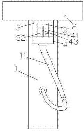
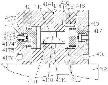
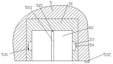
[0024] Such as Figure 1-Figure 7 As shown, a new energy vehicle charging interface and a charging pile of the present invention include an interface piece 51 installed in the automobile wall 5, a support column 1, a beam 2 fixed on the top of the support column 1, and a The clamping part 3 at the bottom of the beam 2 and the charging gun head 4 clamped in the clamping part 3 , the charging gun head 4 includes a plugging part 41 and a handle part 42 fixed at the bottom of the plugging part 41 A counterbore 414 is provided in the top end surface of the insertion part 41, a press sensor 4141 is provided in the counterbore 414, a first sliding cavity 411 is provided in the insertion part 41 below the counterbore 414, The left and right sides of the first sliding chamber 411 are symmetrically provided with a second sliding chamber 412, and the side of the second sliding chamber 412 away from the first sliding chamber 411 is provided with a first sinking groove 413. The second slid...


PUM


Abstract

The invention discloses a charging port and a charging pile for new energy vehicles (NEVs). The charging port and the charging pile comprise a port part mounted in a vehicle wall body, a supporting column, a horizontal beam fixed on the supporting column, a clamping part mounted under the horizontal beam and a charging gun head clamped in the clamping part, wherein the charging gun head comprises a plug-in part and a hand-held part which is fixed to the bottom of the plug-in part; a counterbore is arranged in the top end surface of the plug-in part; a pressure sensor is arranged in the counterbore; a first sliding cavity is arranged in the plug-in part and below the counterbore; second sliding cavities are symmetrically arranged at the two sides of the first sliding cavity; first counter grooves are arranged at the side, away from the first sliding cavity, of the second sliding cavities; first sliding blocks are arranged in the second sliding cavities; slope sliding blocks extending into the first sliding cavity are arranged at the inner side of the first sliding blocks; locking blocks running through the first counter grooves and running through the outer side walls of the plug-in part are arranged at the outer side of the first sliding blocks; a screw rod is arranged in the first sliding cavity; and the bottom of the screw rod is in power connection with a motor. The charging port and the charging pile for the NEVs have the advantages of simple structure, convenient plug-in connection and high stability after the plug-in connection, and can prevent interruption of charging caused by accidental touching.

Description

technical field [0001] The invention relates to the technical field of new energy vehicle charging, in particular to a new energy vehicle charging interface and a charging pile. Background technique [0002] With the continuous growth of the national economy, automobiles have been widely popularized. Traditional automobiles consume a lot of oil resources, emit waste gas and make noise, which has brought serious negative effects on the environment and human health. The awareness of environmental protection is constantly enhanced, clean and environmentally friendly. Electric vehicles replace oil with electricity, which can achieve "zero emission" and low noise, and are an important means to solve energy and environmental problems. With the shortage of oil resources and the development of battery technology, electric vehicles are close to or even superior to traditional fuel vehicles in terms of performance and economy, and have begun to be gradually promoted and applied world...

Claims


Application Information

Patent Timeline
Patent Type & Authority Applications(China)
IPC IPC(8): B60L11/18H02J7/00H01R13/629H01R13/639
CPCB60L53/16B60L53/31H01R13/629H01R13/639H02J7/0045Y02T10/70Y02T10/7072Y02T90/12Y02T90/14
Inventor 骆剑锋
Owner 广州市双岛科技有限公司
Why Eureka
Try Eureka