Micro-flow pumping structure, system and manufacturing method

A manufacturing method and pumping technology, applied in microstructure technology, microstructure devices, manufacturing microstructure devices, etc., can solve problems such as poor stability, and achieve high reliability and simple structure

Inactive Publication Date: 2017-11-10
WEIFANG GOERTEK MICROELECTRONICS CO LTD
View PDF17 Cites 1 Cited by
  • Summary
  • Abstract
  • Description
  • Claims
  • Application Information

AI Technical Summary

Problems solved by technology

[0002] Microfluidic control technology has played an important role in the fields of organic synthesis, microreactors, chemical analysis and biomedicine. Now the most widely used fluid drive technology in microfluidic drive is electroosmotic drive, which has simple structure and convenient operation. , no pulsation, etc., but it is also easily affected by factors such as external electric field strength, channel surface, microfluidic properties, and heat transfer efficiency, and the stability is relatively poor

Method used


Image

  • Micro-flow pumping structure, system and manufacturing method
  • Micro-flow pumping structure, system and manufacturing method
  • Micro-flow pumping structure, system and manufacturing method

Examples


Embodiment 1

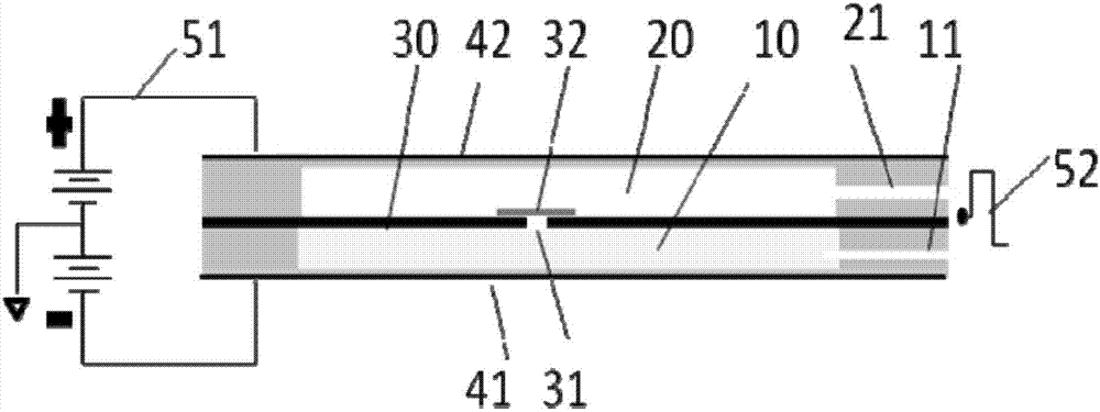
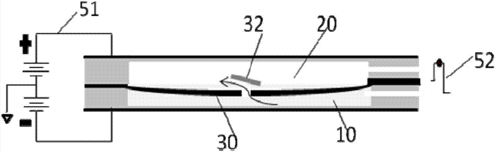
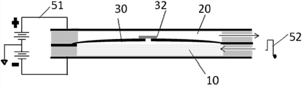
[0028] Such as Figure 7 As shown, a micro-flow pumping structure provided by the first embodiment of the present invention includes: a pump chamber, a power diaphragm 30 disposed in the pump chamber, and a driving device for driving the power diaphragm 30 to move in the pump chamber; The power diaphragm 30 divides the pump cavity into a first chamber 10 and a second chamber 20; the first chamber 10 has a first channel 11 for communicating with the outside, and the second chamber 20 has a channel for communicating with the outside. In the second channel 21 , the power diaphragm 30 has a third channel that opens from the first chamber 10 to the second chamber 20 in one direction. That is to say, the present embodiment divides the pump chamber into a first chamber 10 and a second chamber 20 by setting a power diaphragm 30 in the pump chamber, and the power diaphragm 30 continuously divides the first chamber into the first chamber while moving in the pump chamber. The liquid in ...

Embodiment 2

[0031] Such as Figures 1 to 3 The second embodiment shown is different from the first embodiment in that the power diaphragm 30 is driven by electric field force in the second embodiment. Specifically, the micro-flow pumping structure also includes two conductive plates arranged on both sides of the pump chamber and opposite to the dynamic diaphragm 30. The dynamic diaphragm 30 is a conductor, even if the dynamic diaphragm 30 is located on the two conductive plates. in the electric field. The driving device includes a DC power supply 51 applied to one of the two conductive plates and the dynamic diaphragm 30 , and an AC power supply 52 applied to the other of the two conductive plates and the dynamic diaphragm 30 . Preferably, two conductive plates form the two side walls of the pump chamber, i.e. Figures 1 to 3 On the one hand, the upper and lower side walls can reduce the thickness of the entire micro-flow pumping structure; on the other hand, it can also reduce the proc...

Embodiment 3

[0039] Such as Figure 7 As shown, in the third embodiment of the present invention, the difference from the first embodiment is that the power diaphragm 30 is driven by electromagnetic force in the third embodiment. Specifically, the power diaphragm 30 is provided with ferromagnetic material or magnetic material, and the driving device is an electromagnet arranged outside the pump chamber. By controlling the magnetic force of the electromagnet, the driving of the power diaphragm 30 is realized, and then the liquid pumping is realized. The specific pumping process is similar to the first and second embodiments, and will not be repeated here.


PUM


Abstract

The invention provides a micro-flow pumping structure, system and manufacturing method. The micro-flow pumping structure comprises a pump cavity, a power membrane and a driving device, wherein the power membrane is arranged in the pump cavity, and the driving device drives the power membrane to move in the pump cavity. The pump cavity is divided by the power membrane into a first cavity and a second cavity. The first cavity comprises a first channel, wherein the first channel is used for being communicated with the exterior. The second cavity comprises a second channel, wherein the second channel is used for being communicated with the exterior. A third channel which is opened from the first cavity to the second cavity in a one-way mode is formed in the power membrane. According to the micro-flow pumping structure, the power membrane is arranged in the pump cavity, the pump cavity is divided by the power membrane into the first cavity and the second cavity, liquid in the first cavity is continuously pumped into the second cavity from the third channel and pumped out of the second channel in the process that the power membrane moves in the pump cavity, namely, liquid pumping is achieved through mechanical movement of the power membrane, and therefore the micro-flow pumping structure has the advantages of being simple in structure and high in reliability.

Description

technical field [0001] The invention relates to the field of microfluidic control, in particular to a microfluidic pump structure, system and manufacturing method. Background technique [0002] Microfluidic control technology has played an important role in the fields of organic synthesis, microreactors, chemical analysis and biomedicine. Now the most widely used fluid drive technology in microfluidic drive is electroosmotic drive, which has simple structure and convenient operation. , No pulsation and other advantages, but it is also easily affected by factors such as external electric field strength, channel surface, microfluidic properties and heat transfer efficiency, and its stability is relatively poor. Contents of the invention [0003] The invention aims to provide a micro-flow pumping structure, system and manufacturing method with improved reliability. [0004] In order to achieve the above object, the present invention adopts the following technical solutions: ...

Claims


Application Information

Patent Timeline
Patent Type & Authority Applications(China)
IPC IPC(8): F04B43/04B81B3/00B81C1/00
CPCB81B3/0021B81C1/00158B81C1/00349B81C1/00523B81C2201/013B81C2201/0174F04B43/046
Inventor 李江龙郝红蕾
Owner WEIFANG GOERTEK MICROELECTRONICS CO LTD
Why Eureka
Try Eureka