
Electromagnetic electromechanical coupling circuit tuning vibration absorber

An electromechanical coupling, vibration absorber technology, applied in the direction of shock absorbers, shock absorbers, magnetic springs, etc., can solve the application and development limitations of adjustable dynamic vibration absorbers, complex adjustment control systems, and high design and operation costs. Conducive to integration and miniaturization, low energy consumption of the control system, and intelligent adjustment methods

Active Publication Date: 2017-11-10
HARBIN ENG UNIV
View PDF8 Cites 12 Cited by
  • Summary
  • Abstract
  • Description
  • Claims
  • Application Information

AI Technical Summary

Problems solved by technology

[0004] The adjustment of mass stiffness is usually achieved by changing the mechanical structure, adjusting the position of the center of mass, increasing the prestress of the continuum, and adding additional force. These methods require mechanical adjustment, which requires a large amount of energy. The control system is also relatively complex, and the design and operation costs are very high
The damping is often designed at the beginning of the design, and it is difficult to adjust it during the working process.
These factors limit the application and development of adjustable dynamic vibration absorbers

Method used


Image

  • Electromagnetic electromechanical coupling circuit tuning vibration absorber
  • Electromagnetic electromechanical coupling circuit tuning vibration absorber
  • Electromagnetic electromechanical coupling circuit tuning vibration absorber

Examples


Embodiment Construction

[0026] The present invention is described in detail below in conjunction with accompanying drawing:

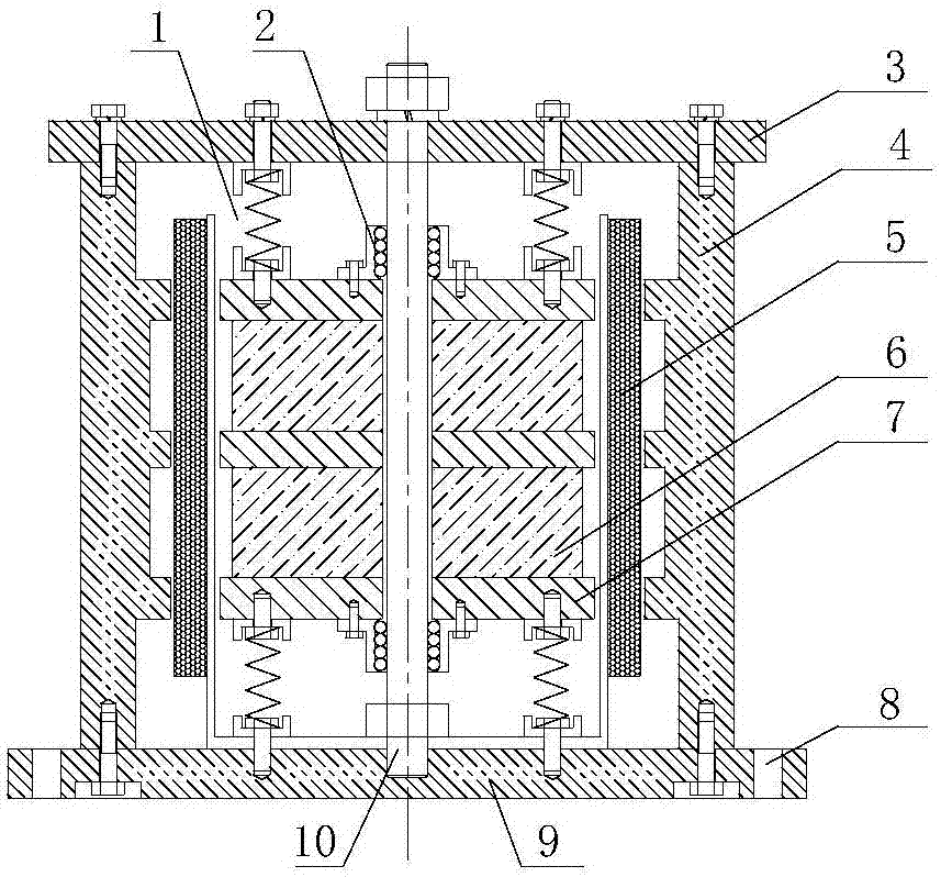
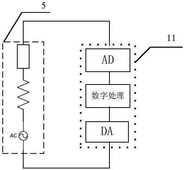
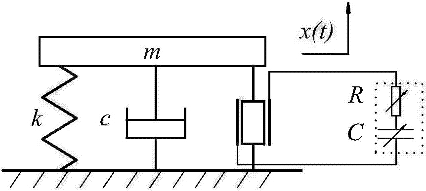
[0027] An electromagnetic electromechanical coupling circuit tuning vibration absorber, which is specifically divided into two parts, one part is as follows figure 1 part of the mechanical structure shown, the other part is as figure 2 part of the circuit shown. The mover of the mechanical structure part is composed of a magnet 6 and an armature 7, and is fixed on the center guide rod 10 through the linear bearings 2 at both ends, which can realize free sliding in the up and down direction, and the upper and lower ends of the mover are respectively preloaded by a compression spring 1 . The stator part is composed of a shell and a coil. The upper 3 and lower 9 plates are used to fix the positions of the guide rods, etc. The side shell 4 can cooperate with the magnetic field circuit of the mover to enhance the magnetic field strength passing through the coil. When the mechan...


PUM


Abstract

Disclosed is an electromagnetic electromechanical coupling circuit tuning vibration absorber. The electromagnetic power generation Faraday principle is adopted, a rotor magnetic field is cut through a coil for converting vibrating kinetic energy into electric energy, then, the coil is connected to a load circuit, and circuit current changes by adjusting impedance characteristics of the load circuit. Due to the fact that the current-carrying coil generates ampere force in a magnetic field, different currents generate ampere force of different magnitudes, different feedback effects can be generated on an existing mechanical system, and therefore different changes of the rigidity and damping of the existing mechanical system are caused through an electromechanical coupling effect. The impedance characteristics can be adjusted through the digital circuit. Compared with traditional mechanical adjustment, adjustment of the electromagnetic coupling mode is rapider and easier, the needed control system is relatively simple and stable, and integration, microminiaturization and low energy consumption of the adjustable vibration absorber can be better achieved.

Description

technical field [0001] The invention belongs to the field of mechanical vibration control, in particular to an electromagnetic electromechanical coupling circuit tuning vibration absorber. Background technique [0002] During mechanical operation, excessive vibration can cause serious damage to structures and machines. In some cases, the suppression of vibration is particularly important, such as vibration problems in aerospace missions. Even small vibrations can last for a long time due to the low damping in weightlessness and vacuum in aerospace. On the other hand, with the improvement of the quality of modern life, people's requirements for the surrounding environment are getting higher and higher, and the control of mechanical vibration is no longer just satisfied with the design standards of mechanical mechanisms, but also needs to fully meet people's needs for the comfort of mechanical products . [0003] The dynamic vibration absorber was invented by Frahm in 1909....

Claims


Application Information

Patent Timeline
IPC IPC(8): F16F6/00F16F7/104
CPCF16F6/00F16F7/104
Inventor 杨铁军喻柳丁李新辉黎文科杨雨浓辛和吴磊黄迪朱丽平徐阳
Owner HARBIN ENG UNIV
Learn More