
Mechanically variable and continuously variable type dual-purpose gearbox for crawler-type tractor

A technology of stepless transmission and tractors, applied in mechanical equipment, belts/chains/gears, fluid transmission devices, etc., to achieve the effects of reducing oil consumption, reducing failure rates, and improving reliability

Active Publication Date: 2017-11-10
YUNZHOU GEARBOX ZHEJIANG PROV
View PDF10 Cites 0 Cited by
  • Summary
  • Abstract
  • Description
  • Claims
  • Application Information

AI Technical Summary

Problems solved by technology

The improvement of the mechanical / continuously variable dual-purpose gearbox of this crawler tractor has not been reported at home and abroad at present

Method used


Image

  • Mechanically variable and continuously variable type dual-purpose gearbox for crawler-type tractor
  • Mechanically variable and continuously variable type dual-purpose gearbox for crawler-type tractor
  • Mechanically variable and continuously variable type dual-purpose gearbox for crawler-type tractor

Examples


Embodiment 1

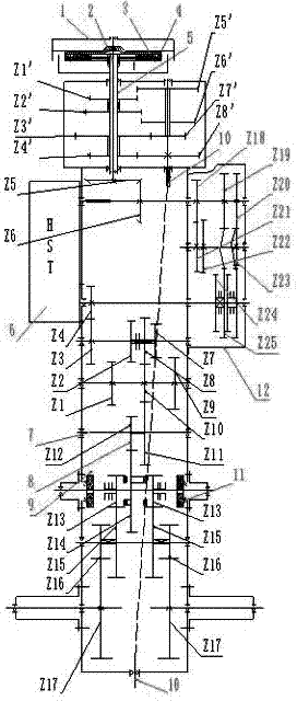
[0024] The present invention is a crawler tractor CVT that adopts the direct connection mode with the power machine, and the power is transmitted to the I-gear driving gear Z1' / I-gear driven gear Z5'→transmission gear CZ7' through the clutch and the hollow transmission shaft 5 / Transmission gear AZ3'→transmission gear BZ4' / transmission gear DZ8'→power output shaft 10; or the power is transmitted to II gear driving gear Z2' / II gear driven gear Z6'→transmission gear by hollow transmission shaft 5 through the clutch CZ7' / transmission gear AZ3'→transmission gear BZ4' / transmission gear DZ8'→power output shaft 10; two speeds are provided for the power output shaft 10.

Embodiment 2

[0026] The transmission force of the continuously variable walking transmission is transmitted from the solid transmission shaft 2 to the transmission gear eZ5 / transmission gear fZ6→hydrostatic continuously variable transmission (HST)6→transmission gear dZ4 / transmission gear cZ3→transmission gear gZ7 / transmission gear iZ9( Or transmission gear bZ2 / transmission gear aZ1, or transmission gear hZ8 / transmission gear jZ10) →Z10 transmission gear j / Z11 transmission gear k→transmission gear lZ12 / central transmission gear Z14→steering gear Z13 / transmission gear mZ15→transmission gear nZ16 / Transmission gear oZ17→drive shaft.

Embodiment 3

[0028]The power of the mechanical variable speed walking transmission is transmitted from the solid shaft 2 to the transmission gear eZ5 / transmission gear fZ6→reverse transmission gear pZ18 / transmission gear sZ21→transmission gear tZ22 / transmission gear vZ24 (high-grade transmission gear qZ19 / transmission gear wZ25, low-speed transmission gear pZ18 / transmission gear sZ21→transmission gear uZ23 / transmission gear rZ20→transmission gear rZ20 / transmission gear wZ25)→transmission gear dZ4 / transmission gear cZ3→transmission gear gZ7 / transmission gear iZ9 (or transmission gear bZ2 / transmission gear aZ1, or transmission Gear hZ8 / transmission gear jZ10)→Z10 transmission gear j / Z11 transmission gear k→transmission gear lZ12 / central transmission gear Z14→steering gear Z13 / transmission gear mZ15→transmission gear nZ16 / transmission gear oZ17→drive shaft.

[0029] Between the central transmission gear Z14 and the steering gears Z13 on both sides, there is a tooth for steering. By turning the...


PUM


Abstract

The invention discloses a mechanically variable and continuously variable type dual-purpose gearbox for a crawler-type tractor. The dual-purpose gearbox is characterized by comprising a power machine flywheel, a clutch friction plate, a gearbox body and a power take-off connecting plate which is arranged between the power machine flywheel and the clutch friction plate and is fixedly connected with the power machine flywheel; and a solid transmission shaft is arranged in the gearbox body, a hollow transmission shaft is arranged on the outer side of the solid transmission shaft in a sleeved mode, one side of the gearbox body is provided with a hydrostatic continuously variable device for continuously variable transmission, and the other side of the gearbox body is provided with an externally-connected box body used for mechanically variable transmission. The mechanically variable and continuously variable type dual-purpose gearbox for the crawler-type tractor has the beneficial effects that the hydrostatic continuously variable device and the externally-connected box body are adopted, the externally-connected box is used for carrying out mechanical speed change operation most of the time, and therefore the mechanical transmission efficiency is improved, and the oil consumption is greatly reduced.

Description

technical field [0001] The invention relates to the technical field of agricultural machinery, in particular to a crawler tractor machinery / continuously variable dual-purpose gearbox. Background technique [0002] Ecological agricultural crawler tractors mostly adopt hydrostatic continuously variable transmission, because the efficiency of hydrostatic continuously variable transmission is lower than that of mechanical transmission, and hydraulic components (especially domestic hydraulic components) are relatively delicate, which is harmful to hydraulic oil and operating environment. There are higher requirements, so the reliability of use is low. The present invention came into being to solve these problems, that is, to carry out mechanical / continuously variable speed change according to the operation requirements, and use mechanical speed change for most of the time to carry out operations, which is beneficial to improve the efficiency of mechanical transmission, and also g...

Claims


Application Information

Patent Timeline
Patent Type & Authority Applications(China)
IPC IPC(8): F16H47/02
CPCF16H47/02
Inventor 徐克旺王超
Owner YUNZHOU GEARBOX ZHEJIANG PROV
Learn More