
Billet feeding buffer device, billet feeding system and operation method thereof

The technology of a buffer device and operation method is applied in the field of billet feeding buffer device and billet feeding system, which can solve the problems of hidden dangers in production safety, large impact force, and increased labor intensity of maintenance personnel, so as to avoid serious deformation, avoid damage, The effect of eliminating production safety accidents

Active Publication Date: 2019-03-15
乌海市包钢万腾钢铁有限责任公司
View PDF7 Cites 0 Cited by
  • Summary
  • Abstract
  • Description
  • Claims
  • Application Information

AI Technical Summary

Problems solved by technology

In the process of use, it will cause the following adverse effects: 1. The simple steel frame blocking mechanism has a small energy absorption and buffering effect on the impact process of the steel billet, resulting in a relatively large impact force on the steel billet against the simple steel frame blocking mechanism, and the steel frame is used for several months. After that, serious deformation will occur, and at the same time, the anchor bolts supporting the simple steel frame blocking mechanism will become loose, which will increase the labor intensity of the maintenance personnel and increase the cost of repair and maintenance equipment; 2. The simple steel frame blocking mechanism is blocking the billet After alignment, the actual alignment effect is not ideal, so that when the steel pusher pushes the steel billet into the heating furnace, the steel billet often shows unevenness, occasionally causing individual billets to seriously deviate from the center line of the heating furnace, and seriously deviate from the center line. When the billet slides in the heating furnace, it will scratch the inner wall of the heating furnace, which will bring safety hazards to production

Method used


Image

  • Billet feeding buffer device, billet feeding system and operation method thereof
  • Billet feeding buffer device, billet feeding system and operation method thereof
  • Billet feeding buffer device, billet feeding system and operation method thereof

Examples


Embodiment Construction

[0032] Exemplary embodiments of the present disclosure will be described in more detail below with reference to the accompanying drawings. Although exemplary embodiments of the present disclosure are shown in the drawings, it should be understood that the present disclosure may be embodied in various forms and should not be limited by the embodiments set forth herein. Rather, these embodiments are provided for more thorough understanding of the present disclosure and to fully convey the scope of the present disclosure to those skilled in the art.

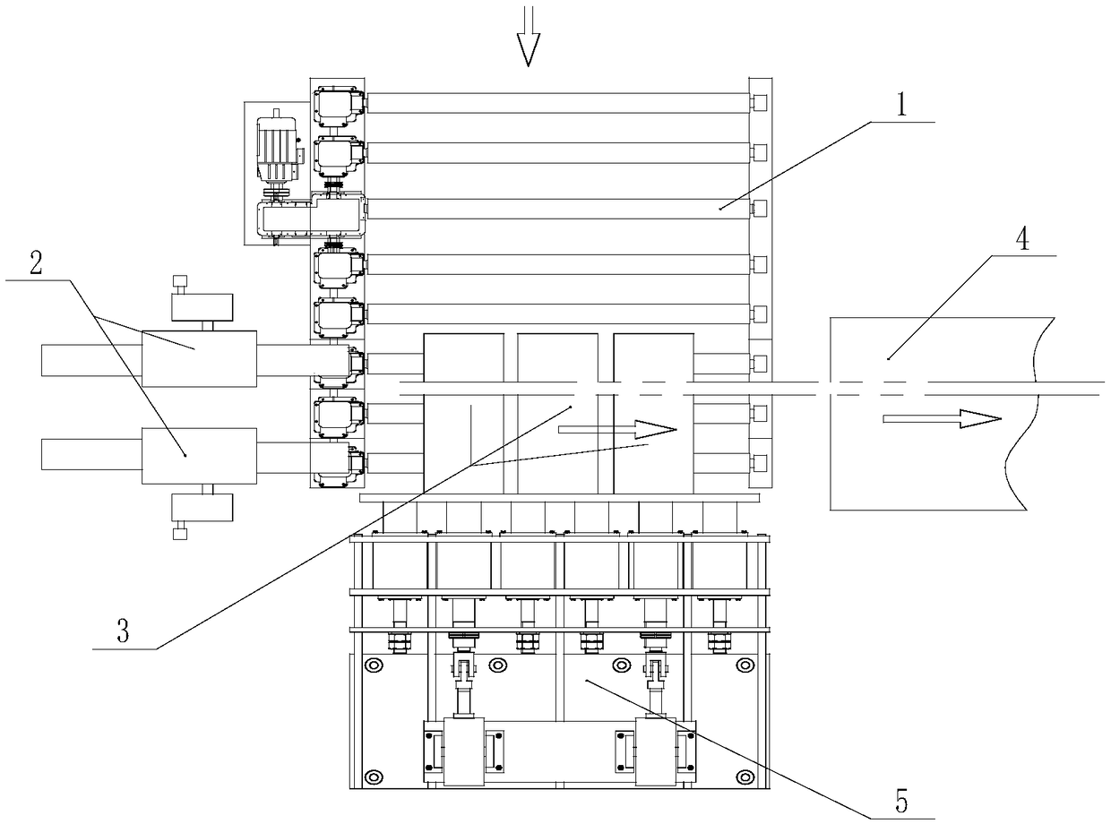
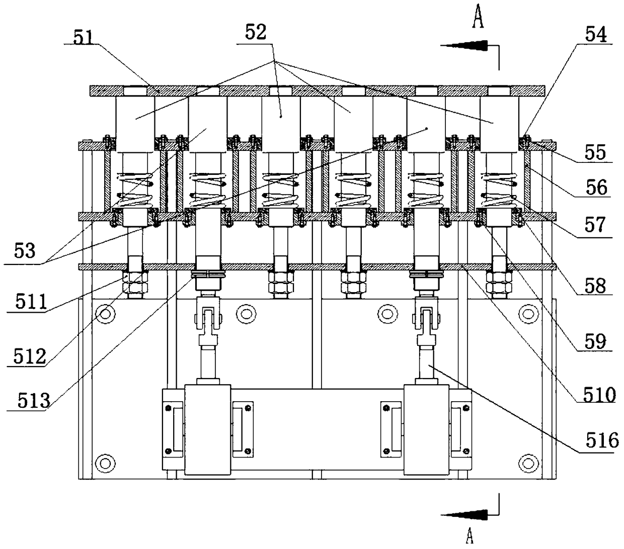
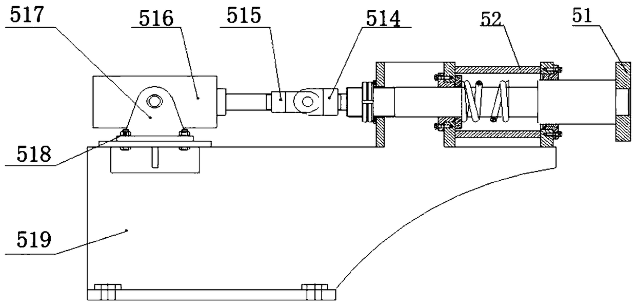
[0033] According to the embodiment of the present invention, such as figure 1 As shown, a billet feeding system is proposed. The billet feeding system includes a feeding roller mechanism 1 , a steel pushing mechanism 2 , a heating furnace 4 and a billet feeding buffer device 5 . Among them, such as figure 2 and image 3 As shown, the billet loading buffer device 5 includes: a cylinder 516 used as a driving member; buffer stopper...


PUM


Abstract

The invention relates to a steel billet feeding buffering device, a steel billet feeding system comprising the steel billet feeding buffering device and a steel billet feeding operation method. The steel billet feeding buffering device comprises a driving component, a fixed static assembly fixedly connected to a civil engineering foundation, an elastic buffering part and a buffering blocking movable assembly, wherein the elastic buffering part is provided with a fixed end fixedly connected to the fixed static assembly, and a jointing end opposite to the fixed end. The buffering blocking movable assembly is connected with the driving component and can move in a reciprocating manner in the contracting direction and the extending direction under the driving effect of the driving component. The jointing end of the elastic buffering part can be jointed with the buffering blocking movable assembly under the condition that the buffering blocking movable assembly moves in the contracting direction, and therefore stress is formed between the fixed static assembly and the buffering blocking movable assembly, and compression pre-tightening force is formed.

Description

technical field [0001] The invention relates to the field of steel processing, in particular to a billet feeding buffer device, a billet feeding system including the billet feeding buffer device and an operation method thereof. Background technique [0002] The billet feeding buffer device is an important device for blocking and aligning the billet before the billet enters the heating furnace in the rolling mill. Push it into the heating furnace for heating (the direction in which the billet is conveyed by the feeding roller mechanism is 90° to the direction in which the billet moves in the heating furnace). The feeding roller mechanism transports three billets at a time, and the weight of each billet is about 3 tons. Every time the billet is transported to the entrance of the heating furnace, the billet feeding buffer device is required to block and align the billet, and the billet buffers the feeding The device receives approximately 500 impacts per day. [0003] The fee...

Claims


Application Information

Patent Timeline
Patent Type & Authority Patents(China)
IPC IPC(8): C21D9/70
CPCC21D9/0018C21D9/70
Inventor 韦剑飞
Owner 乌海市包钢万腾钢铁有限责任公司
Learn More