Current sensor test device and test method

A technology of current sensor and test device, applied in measurement devices, instruments, measurement of electrical variables, etc., can solve the problems of poor current source stability, limited accuracy and stability, and infeasible, to improve measurement accuracy, Ease of measurement and cost reduction

Active Publication Date: 2017-11-14
湖南银河电气有限公司
View PDF6 Cites 10 Cited by
  • Summary
  • Abstract
  • Description
  • Claims
  • Application Information

AI Technical Summary

Problems solved by technology

When the range of the current sensor is relatively large, the output accuracy of the standard current source with large current is affected by internal heating, and the accuracy and stability are severely limited
The output of the current source has a certain error, and the stability of the output of the current source is generally not very good, and it will change with the internal heating and other conditions, which are all unfavorable factors that affect the measurement
[0003] With the continuous development of current sensors, the accuracy of current sensors is also constantly improving, especially the high-precision current sensors of magnetic modulation and flux gates, whose accuracy can reach 1ppm or even higher, while large current sources generally can only achieve The accuracy of the sensor is about 1‰, and the measurement accuracy of the sensor is much higher than the accuracy that the current source can achieve, making the above source-meter method test scheme no longer feasible

Method used


Image

  • Current sensor test device and test method
  • Current sensor test device and test method
  • Current sensor test device and test method

Examples


Embodiment Construction

[0024] The embodiments of the present invention will be described in detail below with reference to the accompanying drawings, but the present invention can be implemented in various ways defined and covered by the claims.

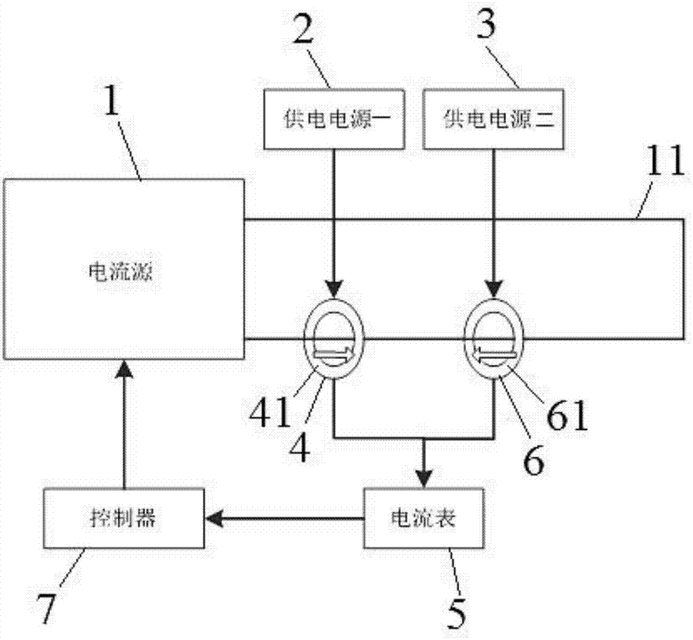
[0025] see figure 1 The current sensor testing device comprises a current source 1, a power supply one 2, a power supply two 3, a standard current sensor 4 and an ammeter 5, and the current source is used to provide the primary side bus current to the standard current sensor and the current sensor 6 to be measured, and the current A current bus 11 is connected between the two output ends of the source, and the current bus is used to pass through the magnetic core A61 of the current sensor to be measured and the magnetic core B41 of the standard current sensor in sequence (including that the current bus first passes through or winds the magnetic core A, the case of passing through or winding the magnetic core B and the current bus first passing through or w...


PUM


Abstract

The invention provides a current sensor test device which comprises a current source (1), a first power supply (2), a second power supply (3), a standard current sensor (4) and an ammeter (5). The current sensor is used to provide primary side bus current for the standard current sensor and a current sensor (6) to be tested. The winding or passing directions of a current bus on the standard current sensor magnetic core and the magnetic core of the current sensor to be tested are opposite, so that the standard current sensor and the current sensor to be tested have opposite current output directions. The ammeter is used to measure the current sum of the standard current sensor and the current sensor to be tested, wherein some or all of the output current of the standard current sensor and the current sensor to be tested are offset. The accuracy of the current sensor to be tested is judged based on the current sum. According to the invention, the accuracy of the test device is limited only by the accuracy of the standard current sensor; the accuracy and stability of the current source and the ammeter have little influence on a test system; the requirements on the accuracy and the stability of the current source and the ammeter are greatly reduced; and the cost is greatly reduced.

Description

technical field [0001] The invention relates to a current sensor calibration technology, in particular, to a current sensor testing device and a testing method. Background technique [0002] Current sensors are widely used in the fields of industry and electric power. The accuracy of current sensors plays a vital role in the accuracy of test results. At present, the accuracy detection method of current sensors generally adopts the source-meter method: using a standard current source to output A current passes through the magnetic core of the current sensor to be tested, and the output current value of the current sensor to be tested is compared with the theoretical value to obtain the accuracy of the current sensor to be tested. The output terminal of the sensor is connected to the ammeter and measured. The theoretical value is obtained by dividing the current value of the primary side or the busbar by the transformation ratio of the standard current sensor. Since the accur...

Claims


Application Information

Patent Timeline
Patent Type & Authority Applications(China)
IPC IPC(8): G01R35/02
CPCG01R35/02
Inventor 刘永刚翟昌伟
Owner 湖南银河电气有限公司
Why Eureka
Try Eureka