Conveniently maintained and overhauled low-voltage cabinet

A low-voltage cabinet and cabinet door technology, applied in the field of low-voltage cabinets, can solve the problems of reducing the maintenance and repair efficiency of technicians, narrow internal space, etc., and achieve the effects of flexible and changeable positions, improved efficiency, and improved convenience.

Active Publication Date: 2017-11-14
ZHEJIANG MAILANG ELECTRIC
View PDF6 Cites 14 Cited by
  • Summary
  • Abstract
  • Description
  • Claims
  • Application Information

AI Technical Summary

Problems solved by technology

[0004] The purpose of the present invention is to solve the disadvantages of the fixed structure of the low-voltage cabinet in the prior art, and the limitation of the side walls on both sides causes the internal space to be narrow, which reduces the efficiency of maintenance and repair by technicians, and proposes a low-voltage cabinet that is easy to maintain and repair

Method used


Image

  • Conveniently maintained and overhauled low-voltage cabinet
  • Conveniently maintained and overhauled low-voltage cabinet
  • Conveniently maintained and overhauled low-voltage cabinet

Examples


Embodiment 1

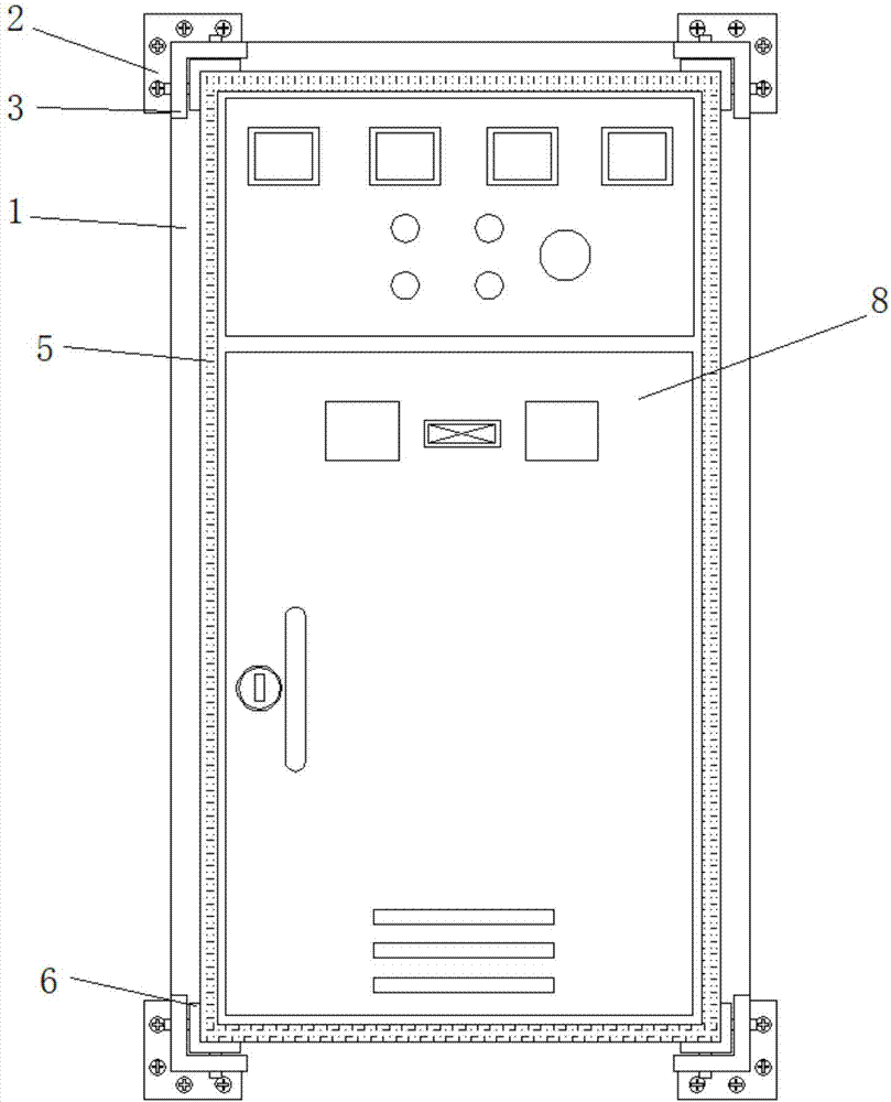
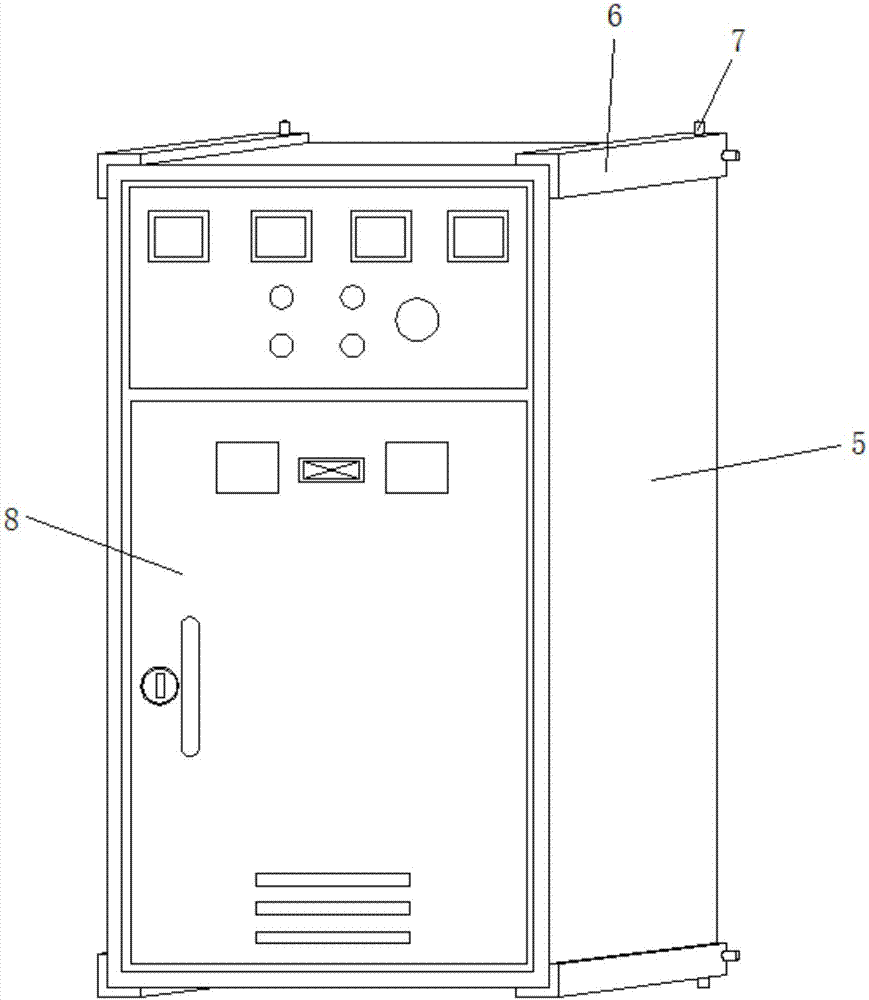
[0027] refer to Figure 1-5 , a low-voltage cabinet that is convenient for maintenance and repair, including a fixing device and a low-voltage cabinet main body 5, the low-voltage cabinet main body 5 is movably installed on the fixing device, the fixing device includes a rectangular installation frame 1, and the four corners of the rectangular installation frame 1 are provided with L-shaped fixing Ears 2, and the four corners of the same side of the rectangular installation frame 1 are fixed with L-shaped slide rails 3, four sets of L-shaped slide rails 3 are vertically arranged with the rectangular installation frame 1, and the two side walls of the L-shaped slide rail 3 are along the length direction Both are provided with sliding limit grooves 4 that run through the side walls;

[0028] The main body 5 of the low-voltage cabinet is a rectangular structure, and the four corners are provided with L-shaped sliding blocks 6 along the width direction, and the side walls of the e...

Embodiment 2

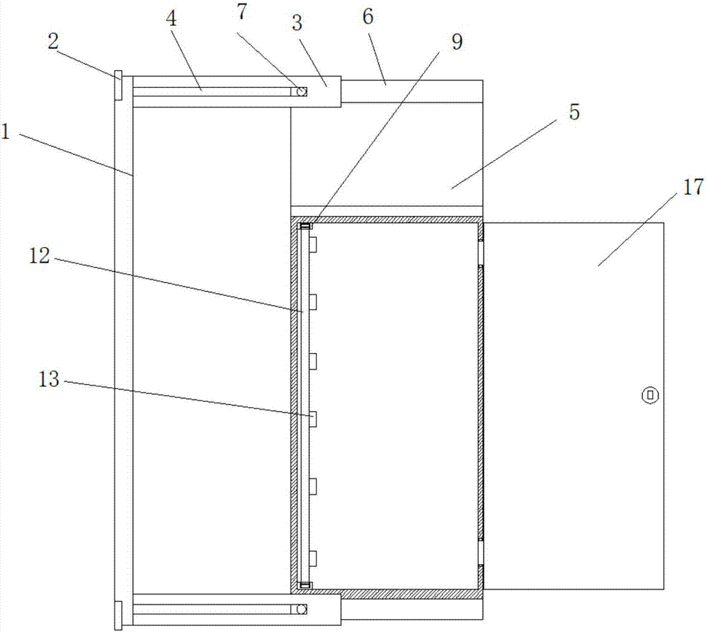
[0031] refer to Figure 6-7, the locking device includes telescopic slots, and the telescopic slots are arranged at both ends of the movable mounting plate 12 away from the side of the supporting shaft 11. Clamping spring 14, and one end of clamping spring 14 away from the bottom of the groove is fixedly connected with clamping column 15, and one end of clamping column 15 away from clamping spring 14 extends to the outside of the telescopic groove through the opening, and is connected with the fixed slot hole 10 One side of the telescopic slot is provided with an adjustment channel running through the side wall along its length direction, and one end of the clamping spring 14 connected with the clamping column 15 is provided with an adjustment rod 16, and the adjustment rod 16 extends to the The outside of the telescoping slot.

[0032] The supporting shaft 11 can drive the movable mounting plate 12 to rotate. When the main body 5 of the low-voltage cabinet is drawn out, mult...

Embodiment 3

[0034] refer to figure 2 and 5 , the length of the four sets of L-shaped slide rails 3 is equal to the width of the main body 5 of the low-voltage cabinet, and the ends of the L-shaped slide rails 3 away from the rectangular installation frame 1 are connected to the limit rod through the rotation of the rotating shaft, and the limit rod is opposite to the main body 5 of the low-voltage cabinet. The position is restricted and fixed.

[0035] The end of the L-shaped sliding track 3 away from the rectangular installation frame 1 is provided with a limit rod, which can pull the main body 5 of the low-voltage cabinet away from the wall surface where it is installed through the L-shaped sliding block 6. Fix the position so that the main body 5 of the low-voltage cabinet can only move within the length of the sliding limit groove 4, preventing the main body 5 of the low-voltage cabinet from sliding out of the L-shaped sliding track 3 at will.


PUM


Abstract

The invention discloses a conveniently maintained and overhauled low-voltage cabinet which comprises a fixing device and a low-voltage cabinet main body, wherein the low-voltage cabinet main body is movably arranged on the fixing device; the fixing device comprises a rectangular mounting frame; L-shaped fixing lugs are arranged at four corners of the rectangular mounting frame; L-shaped sliding rails are fixedly arranged at the four corners of a same side wall of the rectangular mounting frame; four sets of L-shaped sliding rails and the rectangular mounting frame are vertically arranged; and sliding limiting slots penetrating through the side walls are arranged on the two side walls of the L-shaped sliding rails along the length direction. According to the invention, a mounting wall can be taken away and a movable mounting plate is used for taking the inner element out of the low-voltage cabinet main body, so that the space for maintaining and overhauling the low-voltage cabinet main body can be increased for the technician, the limitation of the two side walls of the low-voltage cabinet main body can be avoided and the working efficiency of the maintaining and overhauling of the technician can be increased.

Description

technical field [0001] The invention relates to the technical field of low-voltage cabinets, in particular to a low-voltage cabinet that is convenient for maintenance and repair. Background technique [0002] The switch cabinet is a kind of electrical equipment. The external line of the switch cabinet first enters the main control switch in the cabinet, and then enters the sub-control switch, and each branch is set according to its needs. Such as instruments, automatic controls, motor magnetic switches, various AC contactors, etc., some also have high-voltage room and low-voltage room switch cabinets, high-voltage busbars, such as power plants, etc. load shedding. The main function of switchgear is to switch, control and protect electrical equipment during the process of power generation, transmission, distribution and power conversion in the power system. The components in the switch cabinet are mainly composed of circuit breakers, disconnectors, load switches, operating ...

Claims


Application Information

Patent Timeline
Patent Type & Authority Applications(China)
IPC IPC(8): H02B1/30H02B1/044
CPCH02B1/044H02B1/30
Inventor 厉宏图
Owner ZHEJIANG MAILANG ELECTRIC
Why Eureka
Try Eureka