Mouse catching plate

A conductive plate and body technology, applied in the field of mousetrap, can solve the problems of poor effect and poor practical performance, and achieve the effects of preventing damage, facilitating transportation, and facilitating trading

Inactive Publication Date: 2017-11-17
黄平宋氏心莲心设备制造有限责任公司
View PDF6 Cites 3 Cited by
  • Summary
  • Abstract
  • Description
  • Claims
  • Application Information

AI Technical Summary

Problems solved by technology

However, due to the unique habits of mice themselves, for example, they are very flexible and cunning, and have strong memory and recognition. The stronger it is, there will be some special rodent control devices that are useless and have poor practical performance.

Method used


Image

  • Mouse catching plate
  • Mouse catching plate
  • Mouse catching plate

Examples


no. 1 example

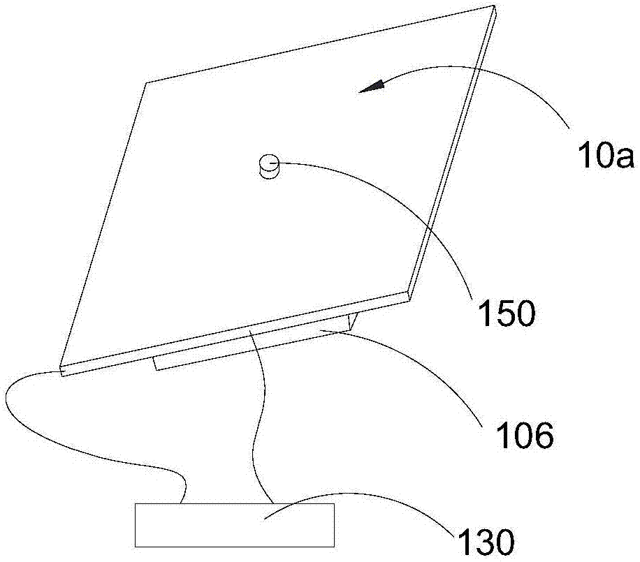
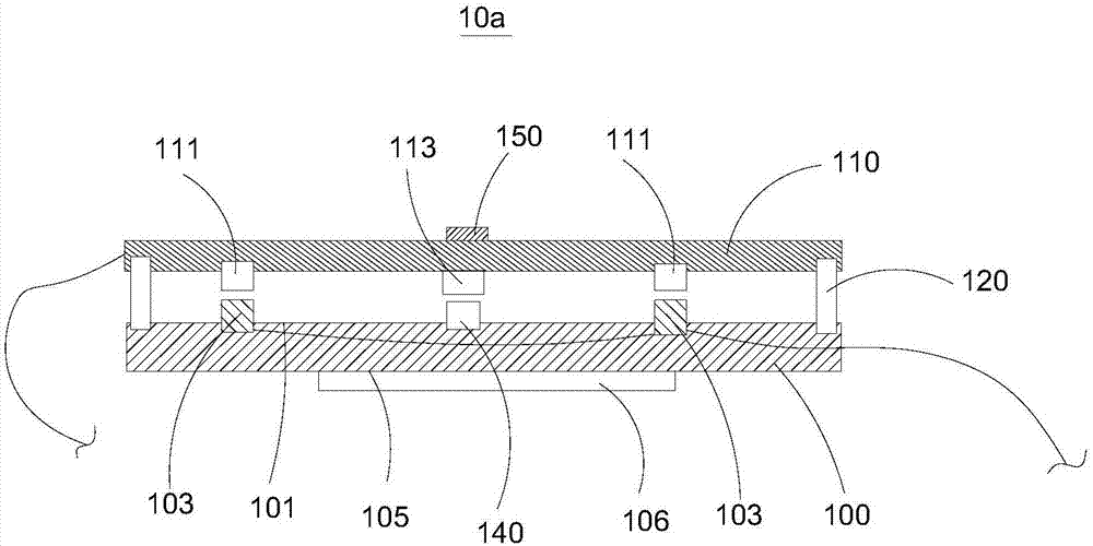
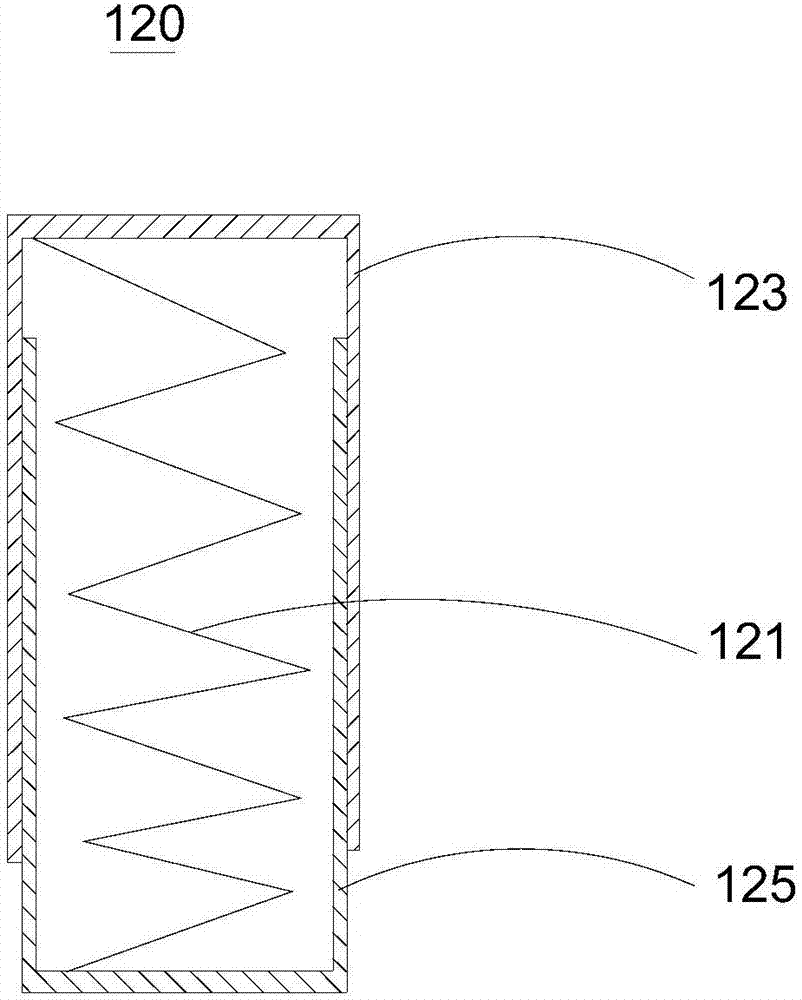
[0026] Please also refer to figure 1 as well as figure 2 , the present embodiment provides a mousetrap 10a, which includes a mousetrap body 100, a conductive plate 110, an elastic mechanism 120, a voltage booster 130, a power supply (not shown), a pressure sensor 140 and a control panel (not shown in the figure) ).

[0027] Among them, see figure 2 The mousetrap body 100 has an opposite first surface 101 and a second surface 105. Specifically, in this embodiment, the first surface 101 is the side of the mousetrap body 100 close to the conductive plate 110, and the second surface 105 is The side of the mousetrap body 100 is away from the conductive plate 110 .

[0028] The first surface 101 is provided with a second wire contact head 103 , preferably, the second wire contact head 103 protrudes from the second surface 105 to facilitate subsequent installation of the elastic mechanism 120 . The second wire contact head 103 is electrically connected to the anode of the boost...

no. 2 example

[0048] see Figure 4 , the present embodiment provides a mousetrap 10b, which is similar to the mousetrap 10a provided in the first embodiment, except that it is also provided with a conductive mousetrap glue layer 160, a protective film (not shown in the figure) ) and packing box (not shown). For parts not described in this embodiment, reference may be made to the specific description in the first embodiment.

[0049] The conductive mouse-trap glue layer 160 is laid on the side of the conductive plate 110 away from the main body of the mouse plate, thereby effectively preventing the mice from escaping from the conductive plate 110 during the process of killing mice, and effectively improving the killing effect.

[0050] Optionally, the thickness of the mouse-trapping glue layer 160 is 0.2-0.8mm, while effectively bonding the mouse, it maintains better electrical conductivity. It is best to use a pressure-sensitive adhesive with better viscosity at high temperature, and ther...


PUM


Abstract

The invention provides a mouse catching plate, and relates to the field of mousetraps. The mouse catching plate comprises a mouse catching plate body, an elastic mechanism and a conductive plate, the mouse catching plate body is connected with the conductive plate through the elastic mechanism, a gap exists between the mouse catching plate body and the conductive plate, the conductive plate is provided with a first wire contact head, the conductive plate is electrically connected with the first wire contact head, the mouse catching plate body is provided with a second wire contact head selectively and electrically connected with the first wire contact head, the second wire contact head is electrically connected with the positive pole of a voltage booster, the conductive plate is electrically connected with the negative pole of the voltage pole, a power supply is electrically connected to the voltage booster, the mouse catching effect is good, and meanwhile power consumption is low, and the work efficiency of the mouse catching plate is effectively improved. The mouse catching plate arranged in a packing box is convenient to transport, and meanwhile the phenomenon that in the transportation process, the mouse catching plate is damaged is effectively prevented.

Description

technical field [0001] The invention relates to the field of mousetrap, and in particular to a mousetrap board. Background technique [0002] Rats often scurry around, biting doors, windows, clothes, wasting food, and spreading diseases. They are extremely harmful to humans. Eliminating rats has always been a topic of great concern to people. The special equipment for extermination of rodents that most people utilize now can play certain effect to extermination of rodents. However, due to the unique habits of mice themselves, for example, they are very flexible and cunning, and have strong memory and recognition. The stronger it is, there will be some special instruments for rodent control that are useless and have poor practical performance. [0003] Therefore be badly in need of a kind of rodent-killing special-purpose apparatus that mouse-catching effect is good. Contents of the invention [0004] The object of the present invention is to provide a mousetrap, which h...

Claims


Application Information

Patent Timeline
Patent Type & Authority Applications(China)
IPC IPC(8): A01M23/38
CPCA01M23/38
Inventor 宋杰
Owner 黄平宋氏心莲心设备制造有限责任公司
Why Eureka
Try Eureka