T-shaped guide rail straightening device with turnover mechanism

A flipping mechanism and straightening technology, applied in the direction of forming tools, metal processing equipment, manufacturing tools, etc., can solve the problems of a lot of labor, low degree of automation, low work efficiency, etc., to ensure the corrective effect, high degree of automation, improve The effect of work efficiency

Inactive Publication Date: 2017-11-17
FOSHAN ZHENGLUE INFORMATION TECH CO LTD
7 Cites 0 Cited by

AI-Extracted Technical Summary

Problems solved by technology

[0003] The T-shaped guide rail is a kind of guide rail. The T-shaped guide rail is composed of a guide arm and fixed arms located on both sides of the guide arm. The T-shaped guide rail needs to be straightened during the processing process, mainly for the straightness of the top surface and side of the guide ...

Abstract

The invention discloses a T-shaped guide rail straightening device with a turnover mechanism. The T-shaped guide rail straightening device comprises a straightening platform and the turnover mechanism, wherein a moving platform is arranged above the straightening platform, a pressing roller is arranged at the bottom of the moving platform, and a first lifting device is arranged above the pressing roller; the turnover mechanism comprises a support frame body, a disc, a gear, a moving seat and a turnover mechanism base; the disc is rotatably connected to the upper part of the support frame body, a fan-shaped gap is formed in the disc, and a groove which is matched with a fixed arm of a T-shaped guide rail is formed in the fan-shaped gap; the gear is rotatably connected with the lower part of the support frame body, and the gear is engaged with gear teeth on the periphery of the disc; and second lifting devices are symmetrically arranged between the moving seat and the support frame body, and a telescopic device which is used for driving the moving seat to move from left to right is installed on the turnover mechanism base. According to the T-shaped guide rail straightening device, the T-shaped guide rail can be accurately turned over in a straightening process, and the degree of automation is high; additionally, the straightening effect is guaranteed by reciprocating rolling and straightening.

Application Domain

Shaping tools

Technology Topic

EngineeringMechanism based +2

Image

  • T-shaped guide rail straightening device with turnover mechanism
  • T-shaped guide rail straightening device with turnover mechanism

Examples

  • Experimental program(1)

Example Embodiment

[0017] The technical solution of the present invention will be described in further detail below in conjunction with specific embodiments.
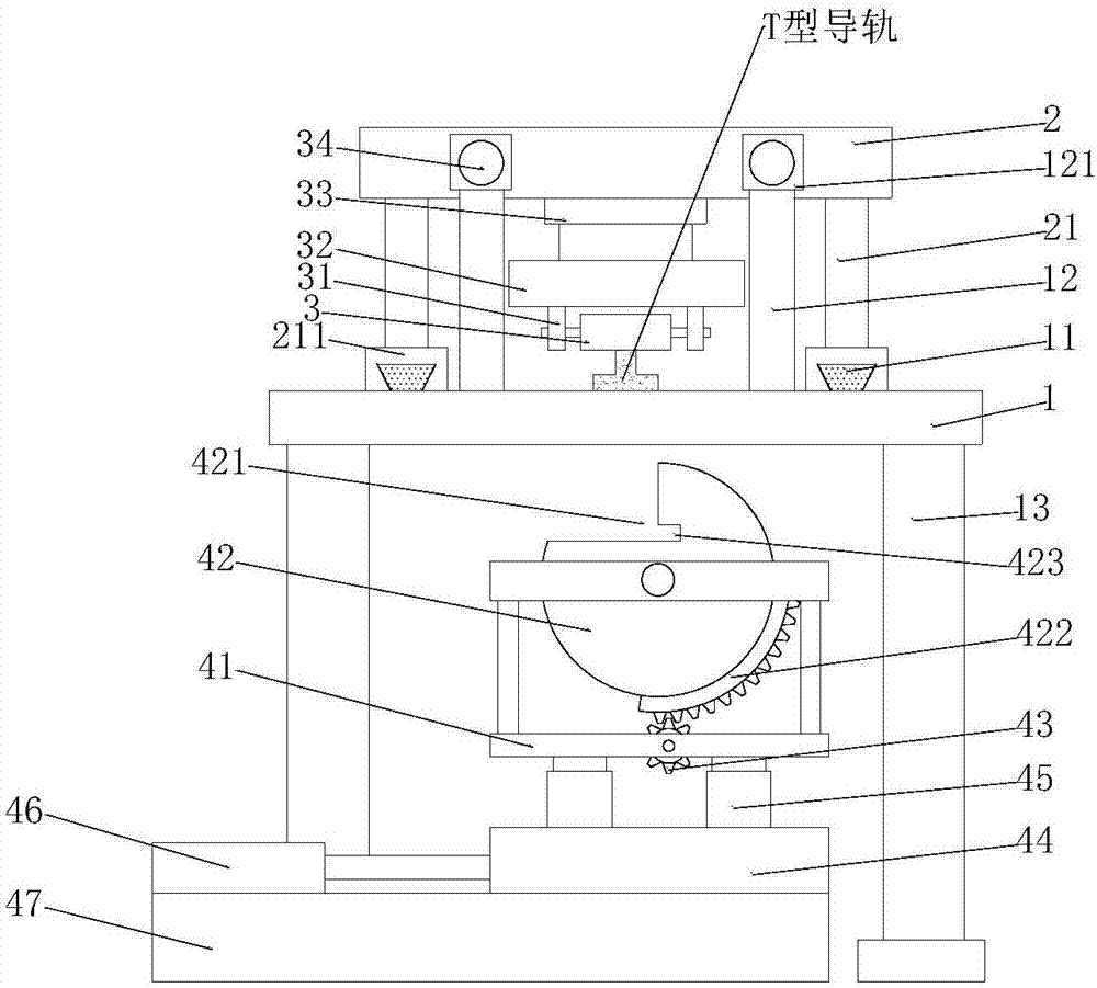
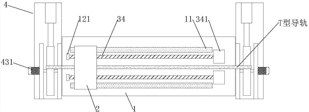
[0018] See Figure 1-2 , A T-rail straightening device with a turning mechanism, comprising a straightening platform 1 and a turning mechanism 4; a moving platform 2 is arranged above the straightening platform 1, and two sides of the bottom of the moving platform 2 are symmetrically connected with column legs 21 , A sliding seat 211 is installed at the bottom of the column leg 21, a sliding rail 11 matching the sliding seat 211 is fixed on the straightening platform 1, the sliding seat 211 is slidingly connected with the sliding rail 11, and the cross section of the sliding rail 11 is an inverted trapezoid. The sliding seat 211 and the sliding rail 11 form a sliding clamping connection, which makes the sliding seat 211 move more smoothly. In addition, two screws 34 are provided symmetrically through the mobile platform 2 and are connected with the threaded holes on the mobile platform 2 (not shown in the figure). (Shown) in cooperation, one end of the screw 34 is connected to the bearing housing 121 to rotate, and the other end is connected to the first motor 341 that drives it to rotate. The bearing housing 121 is installed on the column 12 fixed on the top of the straightening platform 1, and the first motor 341 rotates. Drive the screw 34 to rotate. The screw 34 cooperates with the threaded hole on the mobile platform 2 to drive the mobile platform 2 to move. The bottom of the mobile platform 2 is provided with a pressure roller 3, which is connected to the pressure roller support 31 by rotation, and the pressure roller support 31 is fixed. On the connecting block 32, the connecting block 32 is connected to the output end of the first lifting device 33, the first lifting device 33 is a hydraulic lifting cylinder, and the first lifting device 33 is installed at the bottom of the mobile platform 2;
[0019] The turning mechanism 4 is located on the front and rear sides of the straightening platform 1. The turning mechanism 4 includes a support frame 41, a disc 42, a gear 43, a moving seat 44 and a turning mechanism base 47; the disc 42 is rotatably connected to the support frame On the upper part of the body 41, the disc 42 is provided with a fan-shaped notch 421, a groove 423 is provided in the fan-shaped notch 421, and the groove 423 is matched with the fixed arm of the T-shaped guide rail. The outer ring of the disc 42 is provided with a segment of gear teeth 422; The gear 43 is rotatably connected to the lower part of the support frame 41, the gear 43 meshes with the gear teeth 422, and the gear 43 is also provided with a second motor 431 that drives it to rotate, and the second motor 431 is installed on the outside of the support frame 41; The movable seat 44 is located below the supporting frame 41, and the movable seat 44 is slidably connected to the turning mechanism base 47. Two second lifting devices 45 are symmetrically arranged between the movable seat 44 and the supporting frame 41. The second lifting device 45 is Hydraulic lifting cylinder, the fixed end of the second lifting device 45 is connected to the moving base 44, the movable end of the second lifting device 45 is connected to the support frame 41, the left side of the turning mechanism base 47 is installed with a telescopic device 46, the telescopic device 46 is hydraulically telescopic The movable end of the cylinder and the telescopic device 46 is connected to the moving seat 44. When using, first turn the top surface of the guide arm of the T-shaped guide rail upward, and start the first lifting device 33 to drive the pressure roller 3 to press down, so that the pressure roller 3 is pressed against the T-shaped The guide rail, and then start the first motor 341 to drive the screw 34 to rotate. The screw 34 cooperates with the threaded hole on the mobile platform 2 to drive the mobile platform 2 to move to correct the top surface of the guide arm. After the top surface correction is completed, control the first The lifting device 33 drives the pressure roller 3 to rise, so that the pressure roller 3 is out of contact with the T-shaped guide rail, and then the second lifting device 45 is started to rise, thereby driving the disc 42 to rise and contact the bottom surface of the T-shaped guide rail, and then control the gear 43 to drive the disc 42 is rotated 90° clockwise, the T-shaped rail is turned over and the fixed arm on the right enters the groove 423 to form a fixation, and then the telescopic device 46 is controlled to move to the left so that the side of the guide arm of the T-shaped rail corresponds to the pressure roller 3, and then repeats The correction process corrects the side of the guide arm.
[0020] The working principle of the present invention is:
[0021] When the present invention is in use, the top surface of the guide arm of the T-shaped guide rail is turned up, and the first lifting device 33 is activated to drive the pressure roller 3 to press down, so that the pressure roller 3 presses the T-shaped guide rail, and then the first motor 341 is started to drive the screw. 34 rotates, the screw 34 cooperates with the threaded hole on the mobile platform 2 to drive the mobile platform 2 to move to correct the top surface of the guide arm, and at the same time, the first motor 341 is intermittently controlled in the correcting process to move forward and backward, thereby driving the mobile platform 2 Reciprocating movement to strengthen the correction effect. After the top surface is corrected, the first lifting device 33 is controlled to drive the pressure roller 3 to rise, so that the pressure roller 3 is out of contact with the T-shaped guide rail, and then the second lifting device 45 is started to rise, thereby driving the circle The disk 42 rises to contact the bottom surface of the T-rail, and then the gear 43 drives the disk 42 to rotate 90° clockwise, the T-rail turns 90° clockwise, and the fixed arm on the right enters the groove 423 to form a fix, and then controls the expansion and contraction The device 46 moves to the left so that the side of the guide arm of the T-shaped guide rail corresponds to the pressure roller 3, and then repeats the correction process to correct the side of the guide arm.
[0022] In the present invention, the reciprocating pressing roller 3 is used to roll back and forth the T-shaped guide rail to ensure the correction effect; the setting of the turning mechanism 4 enables the device to flip the T-shaped guide rail, and the degree of automation is high, and the operation is reduced. The work intensity of personnel improves work efficiency.
[0023] The preferred embodiments of the present invention have been described in detail above, but the present invention is not limited to the above-mentioned embodiments. Within the scope of knowledge possessed by those of ordinary skill in the art, various modifications can be made without departing from the purpose of the present invention. Kind of change.

PUM

no PUM

Description & Claims & Application Information

We can also present the details of the Description, Claims and Application information to help users get a comprehensive understanding of the technical details of the patent, such as background art, summary of invention, brief description of drawings, description of embodiments, and other original content. On the other hand, users can also determine the specific scope of protection of the technology through the list of claims; as well as understand the changes in the life cycle of the technology with the presentation of the patent timeline. Login to view more.

Similar technology patents

System and method for forecasting molten steel components in RH refining process in online manner

InactiveCN103382514AGuaranteed Reasonableness and Accuracyhigh degree of automation
Owner:NORTHEASTERN UNIV +1

Flexible production system for micro die casting fitting grinding detection

ActiveCN110385618AImprove flexible production and management levelhigh degree of automation
Owner:CHONGQING INST OF GREEN & INTELLIGENT TECH CHINESE ACADEMY OF SCI

Correction method for children's pelma

InactiveCN109602124AGuaranteed corrective effectEnsure healthy development
Owner:呗的科技成都有限公司

Plastic bag in-half folding bagging machine

Owner:安徽银生电气设备有限公司

Classification and recommendation of technical efficacy words

  • Guaranteed corrective effect
  • high degree of automation

Correction method for children's pelma

InactiveCN109602124AGuaranteed corrective effectEnsure healthy development
Owner:呗的科技成都有限公司

High-fineness urban three-dimensional modeling method

Owner:星际空间(天津)科技发展有限公司

Bolt machining all-in-one machine

Owner:ANHUI LIUFANG ZHONGLIAN MECHANICAL SHARE
Why Eureka
Try Eureka