Two-wing differential flapping micro flapping rotor aircraft

An aircraft, flapping rotor technology, applied in unmanned aircraft, aircraft, micro-aircraft and other directions, can solve the huge difference in lift contribution and transient energy consumption, large wing lift and transient energy consumption, overall energy utilization In order to reduce the maximum power consumption of the wing, improve the energy utilization efficiency, and reduce the requirements

Active Publication Date: 2017-11-17
BEIHANG UNIV
View PDF10 Cites 5 Cited by
  • Summary
  • Abstract
  • Description
  • Claims
  • Application Information

AI Technical Summary

Problems solved by technology

[0005] The present invention aims at flapping both wings in the same direction for the existing miniature flapping rotor aircraft, resulting in extremely large wing lift and transient energy consumption during down-shooting, and very little lift and transient energy consumption during up-shooting. Due to the huge difference in transient energy consumption, large fluctuations in system lift, and low overall energy utilization, a miniature flapping rotor aircraft with differential flapping wings was proposed.

Method used


Image

  • Two-wing differential flapping micro flapping rotor aircraft
  • Two-wing differential flapping micro flapping rotor aircraft

Examples


Embodiment Construction

[0025] The present invention will be further described in detail with reference to the accompanying drawings and embodiments.

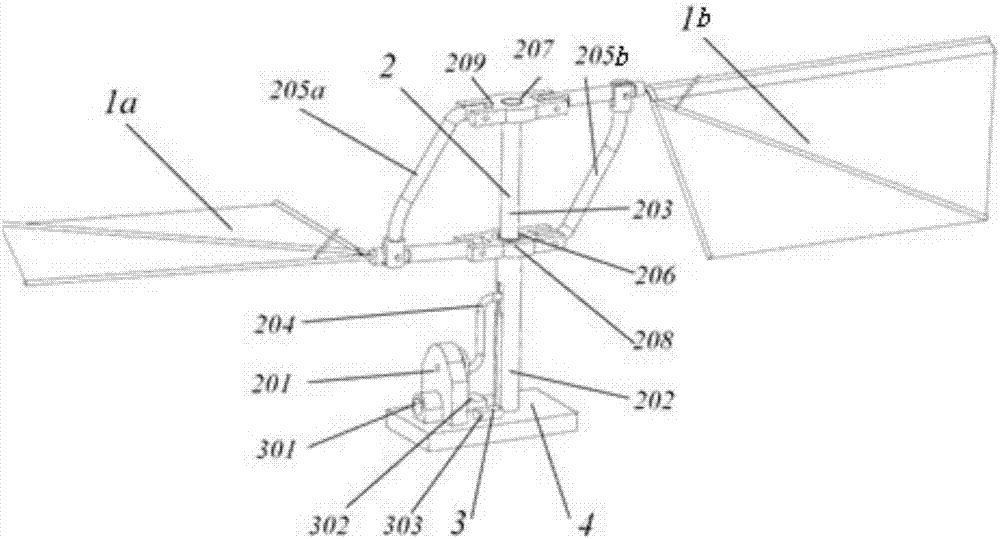
[0026] The present invention is a miniature flapping rotor aircraft with differential flapping of two wings. The left and right wings are flapped differentially, and the flapping difference is about 180 degrees, that is, when one wing flaps downwards, the other flaps upwards. When the average lift is kept constant during flapping of the wings at the same frequency, the lift is more uniform throughout the flapping cycle, and the maximum output power of the motor only needs to be slightly greater than the maximum power of a single wing when flapping down, which effectively reduces a During the flapping process, the maximum power consumption of the wing and the transient lift fluctuation can significantly improve the energy utilization efficiency of the aircraft.

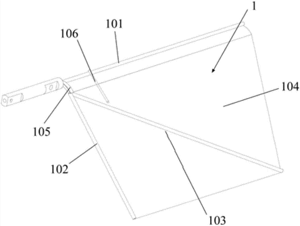
[0027] Described miniature flapping rotor aircraft, such as figure 1 As shown, it include...


PUM


Abstract

The invention discloses a two-wing differential flapping micro flapping rotor aircraft, and relates to the field of micro aircrafts. The two-wing differential flapping micro flapping rotor aircraft comprises wings, a transmission mechanism, a power device and a base. The power device and the transmission mechanism are fixed on the base. The two wings are fixed to the two ends of the transmission mechanism correspondingly. During working, a micro motor in the power device supplies power to drive an inner rod of the transmission mechanism to ascend and descend, so that two wing connecting rods simultaneously move in the opposite directions, the pair of wings arranged symmetrically is driven to move downward and upward alternately, and differential flapping is achieved. According to the two-wing differential flapping micro flapping rotor aircraft, it is ensured that the average lift force in the flapping process with the same frequency of the wings is unchanged, wing transient lift force fluctuations are reduced significantly, the lift force is more even within the whole flapping cycle, requirements for output power of the motor are reduced effectively, and the energy utilizing efficiency is improved significantly.

Description

technical field [0001] The invention relates to the field of micro-aircraft, in particular to a micro-flapping-rotor aircraft with differential flapping of two wings. Background technique [0002] Since the 1990s, with the continuous improvement of traditional aircraft design technology, people have been exploring the mechanism of animal flight and swimming more and more deeply, and the rapid development of microelectronics technology has led to the rapid development of the field of micro air vehicle design. , has broad application prospects in national security and national economic construction, and is applied to tasks such as reconnaissance, communication, exploration and assistance in rescue under complex environmental conditions. [0003] The patent application whose publication number is CN 101492093: "Design Method of Flapping Rotor and Miniature Flapping Rotor Aircraft Designed by Using the Method" discloses a miniature flapping rotor aircraft. supply. MAVs are lig...

Claims


Application Information

Patent Timeline
Patent Type & Authority Applications(China)
IPC IPC(8): B64C33/00B64C33/02B64C39/02
CPCB64C33/00B64C33/02B64C39/028B64U10/40B64U50/19
Inventor 吴江浩周超张艳来
Owner BEIHANG UNIV
Why Eureka
Try Eureka