Eureka AIR delivers breakthrough ideas for toughest innovation challenges, trusted by R&D personnel around the world.

Utility tunnel and construction method thereof

A technology of integrated pipe gallery and combined wall, applied in artificial islands, water conservancy projects, infrastructure projects, etc., can solve the problems of long construction period, large damage to the surrounding environment, large resource consumption, etc., to avoid steel bar binding and formwork. , easy to transport and on-site assembly, improve the effect of construction efficiency

Pending Publication Date: 2017-11-17
陕西建筑产业投资集团有限公司
View PDF8 Cites 0 Cited by
  • Summary
  • Abstract
  • Description
  • Claims
  • Application Information

AI Technical Summary

Problems solved by technology

[0002] At present, my country's comprehensive pipe gallery technology is mainly cast-in-place structure and prefabricated structure. Among them, the cast-in-place structure adopts the traditional house construction method, and the technological process is steel bar binding, formwork support, pouring and vibration. Because, there are generally problems such as long construction period, large resource consumption, significant impact by weather, great damage to the surrounding environment, and difficulty in guaranteeing construction quality.
The prefabricated structure is to prefabricate the comprehensive pipe gallery in sections, and then transported to the construction site by a transport vehicle for assembly. Its materials are mainly steel bars and concrete. It is characterized by convenient construction and short construction period, but there are many joints. Difficulty in assembly technology and complex joint waterproofing process and its large tonnage, limited transportation height and difficulties in the transportation process

Method used


Image

  • Utility tunnel and construction method thereof
  • Utility tunnel and construction method thereof
  • Utility tunnel and construction method thereof

Examples


Embodiment Construction

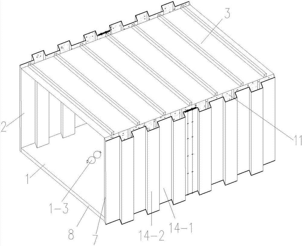
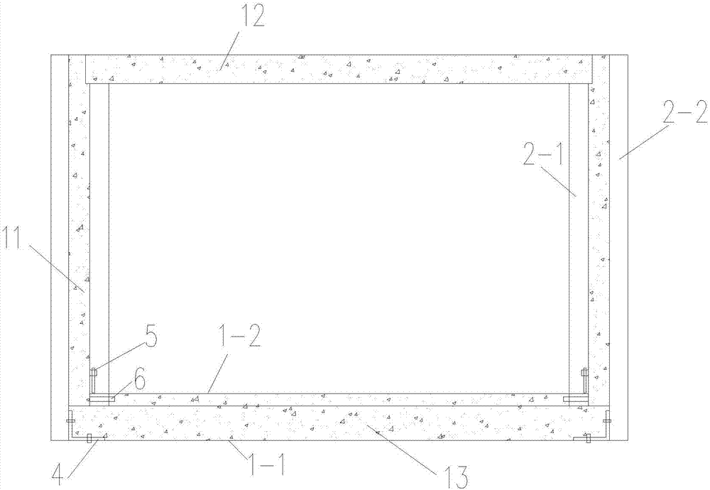
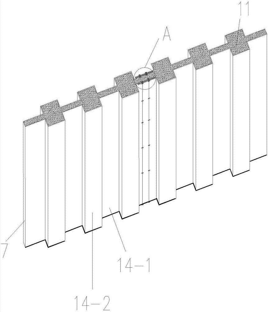
[0042] Such as figure 1 , figure 2 and image 3 A comprehensive pipe gallery shown includes a horizontally arranged rectangular bottom plate 1, a rectangular top plate 3 arranged in parallel above the rectangular bottom plate 1, and two corrugated composite walls 2 vertically arranged between the rectangular bottom plate 1 and the rectangular top plate 3 respectively, The two corrugated composite walls 2 are arranged symmetrically and are respectively arranged on the left and right sides of the rectangular bottom plate 1; the rectangular bottom plate 1, the rectangular top plate 3 and the two corrugated composite walls 2 block out a corridor channel; The cross-section of the corridor passage is a rectangular cross-section;

[0043]Each of the corrugated composite walls 2 includes a corrugated composite board, and the corrugated composite board is composed of a symmetrically arranged inner corrugated board 2-1 and an outer corrugated board 2-2, and the inner corrugated board...


PUM


Abstract

The invention discloses a utility tunnel and a construction method thereof. The utility tunnel comprises a horizontal arranged rectangular base plate, a rectangular top plate horizontally arranged above the rectangular base plate, and two corrugated compound walls vertically arranged between the rectangular base plate and the rectangular top plate, and the two corrugated compound walls are symmetrically arranged on the left side and the right side of the rectangular base plate respectively; the rectangular base plate, the rectangular top plate and the corrugated compound walls surrounds a tunnel channel. The construction method comprises the steps of digging a foundation pit where the construction tunnel locates, assembling boards, pouring concrete and back-filling the foundation pit. According to the utility tunnel, the corrugated compound walls are adopted for the side walls, and protruding portions of the corrugated compound walls have the effect of constructional columns. According to the construction method of the utility tunnel, concrete pouring is conducted on the scene, and joint cracks between tunnel segments are avoided.

Description

technical field [0001] The invention belongs to the technical field of construction of a comprehensive pipe gallery, and in particular relates to a comprehensive pipe gallery and a construction method thereof. Background technique [0002] At present, my country's comprehensive pipe gallery technology is mainly cast-in-place structure and prefabricated structure. Among them, the cast-in-place structure adopts the traditional house construction method, and the technological process is steel bar binding, formwork support, pouring and vibration. Because, there are generally problems such as long construction period, large resource consumption, significant impact by weather, great damage to the surrounding environment, and difficulty in guaranteeing construction quality. The prefabricated structure is to prefabricate the comprehensive pipe gallery in sections, and then transported to the construction site by a transport vehicle for assembly. Its materials are mainly steel bars an...

Claims


Application Information

Patent Timeline
IPC IPC(8): E02D29/045
CPCE02D29/10
Inventor 李卫军苏宝安李泽亮崔国静张磊师莹莹苏衍江
Owner 陕西建筑产业投资集团有限公司
Why Eureka
Eureka Blog
Learn More