Automatic installation equipment of sewage inspection well special for drainage pipeline system

A technology for automatic installation and drainage pipes, which is applied in the sewer system, waterway system, water supply device, etc., and can solve the problems of complicated operation, inability to provide fixed facilities, and low labor intensity.

Inactive Publication Date: 2017-11-17
俞樑兵
View PDF0 Cites 9 Cited by
  • Summary
  • Abstract
  • Description
  • Claims
  • Application Information

AI Technical Summary

Problems solved by technology

[0003] In order to solve the above problems, the present invention provides an automatic installation equipment for sewage inspection wells dedicated to drainage pipeline systems, which can solve the existing problems in the installation process of existing cement sewage inspection wells that need to be installed manually with the help of existing lifting equipment, which requires manual installation. Conveying cement sewage inspection wells with the help of existing mobile equipment requires manual adjustment of fixed lifting tools according to cement sewage inspection wells of different specifications. The manual installation of cement sewage inspection wells with existing lifting equipment is complicated. Manual transportation with existing mobile equipment There are potential safety hazards in cement sewage inspection wells. Existing mobile equipment cannot provide safe fixed facilities, which threatens the personal safety of staff. Manual adjustment of fixed tools is labor-intensive and low in efficiency. Mechanization and automation of cement inspection wells can be realized. The installation function can effectively limit the cement sewage inspection well, without manual adjustment of fixing tools, there is no potential safety hazard, and it has the advantages of good stability, low labor intensity and high work efficiency.

Method used


Image

  • Automatic installation equipment of sewage inspection well special for drainage pipeline system
  • Automatic installation equipment of sewage inspection well special for drainage pipeline system
  • Automatic installation equipment of sewage inspection well special for drainage pipeline system

Examples


Embodiment Construction

[0027] In order to make the technical means, creative features, goals and effects achieved by the present invention easy to understand, the present invention will be further elaborated below in conjunction with specific illustrations.

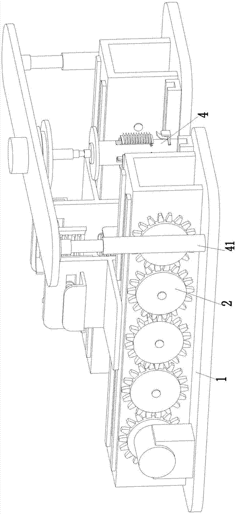
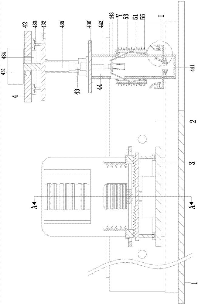
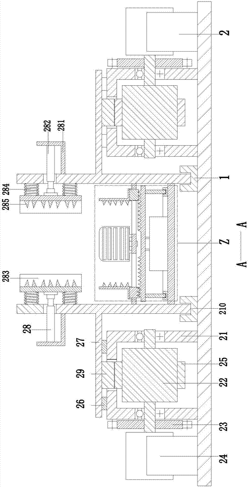
[0028] Such as Figure 1 to Figure 6 As shown, an automatic installation device for sewage inspection wells dedicated to drainage pipeline systems includes a base plate 1, the front end of the base plate 1 is an open structure, and two mobile devices 2 are symmetrically installed on the left and right sides of the base plate 1. Between the two mobile devices 2 A locking device 3 is installed between them. The two moving devices 2 can drive the locking device 3 to move. The locking device 3 can lock the cement sewage inspection well to avoid accidents during the movement. The front end of the bottom plate 1 A fixed lifting device 4 is provided, and the fixed lifting device 4 can automatically install the cement material sewage inspection well to...


PUM


Abstract

The invention relates to an automatic installation equipment for a special sewage inspection well for a drainage pipeline system, which includes a bottom plate, two moving devices are symmetrically installed on the top of the bottom plate, a locking device is installed between the two moving devices, and a fixed lifting device is installed at the front end of the bottom plate device, two mobile devices, a locking device and a fixed lifting device are used in conjunction with each other to complete the mechanized automatic installation process of the sewage inspection well. The invention can solve the problems existing in the installation process of the existing cement sewage inspection wells that need to be manually installed with the help of existing hoisting equipment, need to be manually transported by existing mobile equipment to the cement material sewage inspection wells, and need to be manually installed according to different specifications of cement sewage inspection wells The inspection well adjusts the fixed lifting tools. The existing mobile equipment cannot provide safe fixed facilities. Manual adjustment of the fixed tools is labor-intensive and low in efficiency. It can realize the mechanized and automatic installation function of the cement inspection well.

Description

technical field [0001] The invention relates to the technical field of drainage pipelines, in particular to an automatic installation device for special sewage inspection wells for drainage pipeline systems. Background technique [0002] Sewage inspection wells are inspection wells set up on the drainage pipeline system for inspection and cleaning of pipelines. At the same time, it also plays a ventilation role in connecting pipe sections and piping systems. The pipe sections between two adjacent wells should be on a straight line. Therefore, inspection wells need to be set up at the places where the pipe section changes, the slope changes, the junctions, and the elevation changes, and inspection wells need to be set up in sections on too long straight pipe sections. Well, according to the diameter of the pipe and the type of rain and sewage, the interval between the sections is specified. The sewage detection well is convenient for the staff to clean up the sundries accumu...

Claims


Application Information

Patent Timeline
Patent Type & Authority Applications(China)
IPC IPC(8): E03F3/06E03F5/02
CPCE03F3/06E03F5/02
Inventor 俞樑兵
Owner 俞樑兵
Why Eureka
Try Eureka