Supercharge Your Innovation With Domain-Expert AI Agents!

Pipeline low-pressure protection device

A low-pressure protection device and pipeline technology, which is applied in the direction of valve devices, safety valves, engine components, etc., can solve the problems affecting the normal operation of pipelines and the complex structure of pipeline low-pressure protection devices, and achieve simple structure and isolation of fluid pipelines , good sealing effect

Inactive Publication Date: 2017-11-17
郁华
View PDF0 Cites 0 Cited by
  • Summary
  • Abstract
  • Description
  • Claims
  • Application Information

AI Technical Summary

Problems solved by technology

[0002] In the fluid pipeline, if the fluid pressure in the pipeline is too low, it will affect the normal operation of the pipeline. Therefore, it is necessary to control the low pressure of the fluid in the fluid pipeline. The structure of the existing pipeline low pressure protection device is relatively complicated.

Method used


Image

  • Pipeline low-pressure protection device

Examples


Embodiment Construction

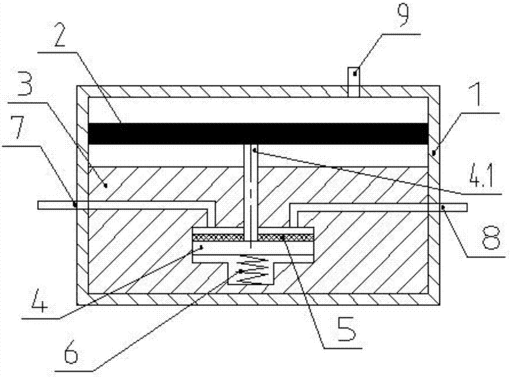
[0011] The present invention will be further described below according to the accompanying drawings and in conjunction with the embodiments.

[0012] The pipeline low-voltage protection device shown in the accompanying drawings includes a housing 1, a diaphragm 2, a valve seat 3, a piston 4, a spring 6, and a gasket 5; the diaphragm 2 is arranged in the inner cavity of the housing 1, and the outer wall of the diaphragm 2 Cooperate with the inner cavity of the housing 1 to divide the inner cavity of the housing 1 into an upper cavity and a lower cavity; the valve seat 3 is set under the lower cavity of the inner cavity of the housing 1; the central axis of the piston 4 is vertically installed in the piston hole in the middle of the valve seat 3 Among them, the piston rod 4.1 with the vertical center axis on the piston 4 penetrates upwards through the valve seat 3, and the sealing gasket 5 is set on the piston 4, and the sealing gasket 5 is installed on the upper end surface of t...


PUM


Abstract

The invention discloses a pipeline low-voltage protection device, which comprises a casing, a diaphragm, a valve seat, a piston, and a spring; the diaphragm is arranged in the inner cavity of the casing, and the outer wall of the diaphragm cooperates with the inner cavity of the casing to divide the inner cavity of the casing into two parts. Upper and lower chambers; the valve seat is set under the lower chamber of the inner cavity of the shell; the central axis of the piston is vertically installed in the piston hole in the middle of the valve seat, and the piston rod with the vertical central axis of the piston goes upward through the valve seat; the spring is arranged under the piston , Push the piston upwards so that the upper end surface of the piston rod is in contact with the lower end surface of the diaphragm; the side wall of the piston hole of the valve seat is provided with holes I and II connecting the side surface of the valve seat and the upper end surface of the piston hole; The inside of the seat is not connected; the housing is provided with an interface III communicating with the upper cavity of the inner cavity of the housing; the further improvement is that: the upper end of the piston is provided with a sealing gasket covering the communication hole I and hole II on the upper end surface of the piston hole. The invention has a simple structure and can play a better role in low-voltage protection.

Description

technical field [0001] The invention relates to a pipeline pressure protection device, in particular to a pipeline low pressure protection device. Background technique [0002] In the fluid pipeline, if the fluid pressure in the pipeline is too low, the normal operation of the pipeline will be affected. Therefore, it is necessary to control the low pressure of the fluid in the fluid pipeline. The structure of the existing pipeline low pressure protection device is relatively complicated. Contents of the invention [0003] The invention aims at the deficiencies of the prior art, and proposes a pipeline low pressure protection device with a simple structure. [0004] The present invention achieves technical goals through the following technical solutions. [0005] The improvement of the pipeline low-voltage protection device is that it includes a housing, a diaphragm, a valve seat, a piston, and a spring; The cavity is divided into an upper cavity and a lower cavity; the v...

Claims


Application Information

Patent Timeline
Patent Type & Authority Applications(China)
IPC IPC(8): F16K17/04
CPCF16K17/0413
Inventor 郁华
Owner 郁华
Features
  • R&D
  • Intellectual Property
  • Life Sciences
  • Materials
  • Tech Scout
  • Unparalleled Data Quality
  • Higher Quality Content
  • 60% Fewer Hallucinations
Learn More