
Adjustment device and method for measuring nanometer non-contact optical fiber sensor

An optical fiber sensor and adjustment device technology, which is applied in the measurement device, the use of optical devices, the testing of machine/structural components, etc., can solve the problems of small distribution range, small measuring range, large structure size, etc., and achieve the effect of accurate displacement

Active Publication Date: 2017-11-17
SHAANXI UNIV OF SCI & TECH
View PDF4 Cites 1 Cited by
  • Summary
  • Abstract
  • Description
  • Claims
  • Application Information

AI Technical Summary

Problems solved by technology

On the other hand, the range of surface pressure distribution and deformation distribution on the bonding surface is very small, ensuring that the optical fiber sensors are within the measurement range. Installing multiple optical fiber sensors on the narrow bonding surface has obvious shortcomings with the existing sensor adjustment device.
[0004] Existing devices that can be used for precise adjustment of high-precision sensors all use an adjustment frame or an adjustment table with a two-dimensional or three-dimensional spiral micrometer. Requirements for the installation and operation position of installation in inner and narrow places and simultaneous measurement of multiple sensors
The displacement measurement of the joint surface is to place the lower test piece on the experimental square box, and the optical fiber sensor is installed on the lower test piece through the hole in the upper part of the square box, and multiple installations must be installed at the same time, and adjustment space must be reserved. The existing adjustment clip The head cannot meet the space and adjust the space requirements
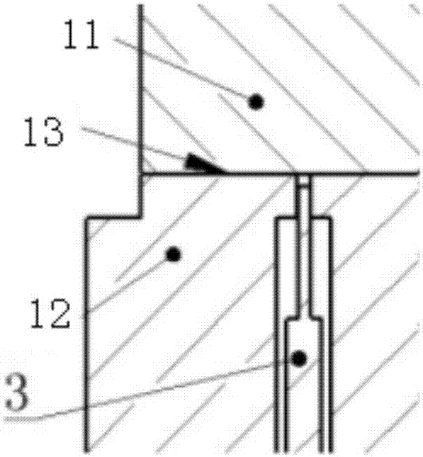
like figure 1 As shown, when testing the joint surface stiffness, it is necessary to measure the deformation of the joint surface under the external load. Open a hole on the test piece to insert the optical fiber sensor from the bottom. In order to ensure that the appearance of the joint surface is not damaged as much as possible, the diameter of the optical fiber probe is very small, the smallest diameter is only 0.17mm, and the aperture of the corresponding sensor on the lower test piece is only 0.2mm. mm; and the range of the nano-scale fiber optic sensor is very small, the position of the fiber sensor needs to be adjusted to the range before measurement, if the fiber sensor is directly installed and inserted into the through hole, the fiber sensor head can only be ensured by manually controlling the insertion depth of the fiber sensor. The distance from the bottom to the joint surface cannot be precisely controlled to ensure that the distance from the measurement surface is within the range of measurement. If it is adjusted directly for many times, the sensor head may be damaged.
The existing adjustment device cannot realize the pre-adjustment before the experimental assembly to meet the needs of small measuring ranges

Method used


Image

  • Adjustment device and method for measuring nanometer non-contact optical fiber sensor
  • Adjustment device and method for measuring nanometer non-contact optical fiber sensor
  • Adjustment device and method for measuring nanometer non-contact optical fiber sensor

Examples


Embodiment Construction

[0026] Below in conjunction with accompanying drawing, the present invention is described in further detail:

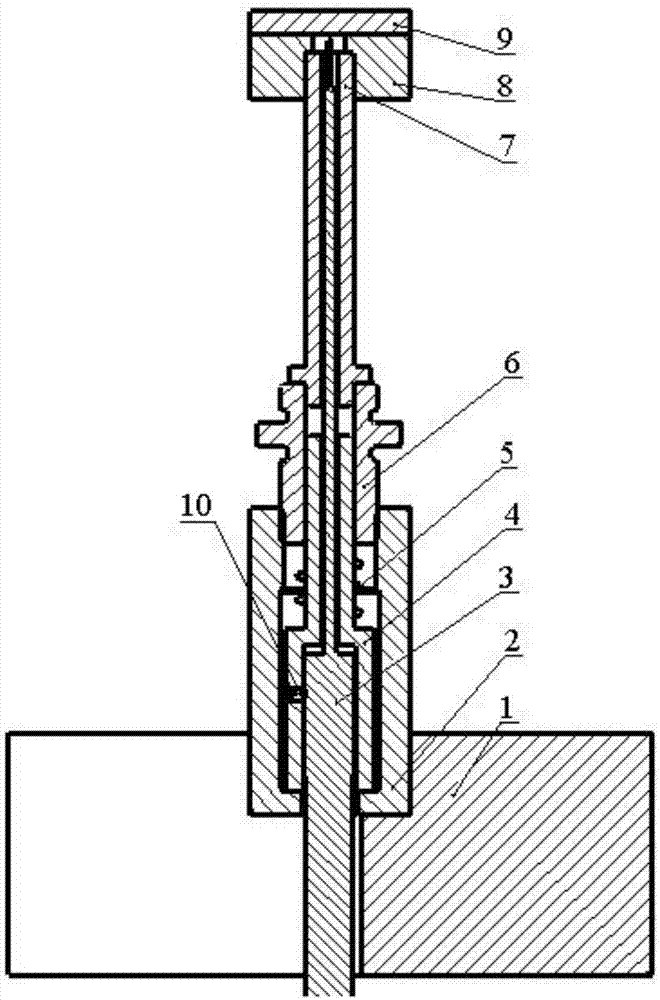
[0027] see Figure 1 to Figure 5 , the adjustment device for nanoscale non-contact optical fiber sensor measurement, including the adjustment nut 2, the lower part of the adjustment nut 2 is interspersed with an optical fiber sensor 3, the upper part is interspersed with a fixed rod 4, and the optical fiber sensor 3 is installed on the fixed rod through the hole below the fixed rod 4 In the rod 4, and the optical fiber sensor 3 is fixed with the fixed rod 4 through the set screw 10, the upper part of the fixed rod 4 is provided with a fixed screw 6, and the outer side of the lower part of the fixed screw 6 is threadedly connected with the upper inner side of the adjustment nut 2, and fixed A spring 5 is arranged between the bottom of the screw rod 6 and the fixed rod 4, the upper part of the fixed screw rod 6 is connected with a fine-tuning cylinder 7, the upper part ...


PUM


Abstract

The invention discloses an adjustment device and method for measuring a nanometer non-contact optical fiber sensor. The adjustment device comprises an adjustment nut. An optical fiber sensor is arranged in the lower part of the adjustment nut in a penetrating manner, and a fixing rod is arranged in the upper part in a penetrating manner. The optical fiber sensor is installed in the fixing rod through a hole below the fixing rod. The upper part of the fixing rod is sleeved with a fixing screw rod, and the outer side of the lower part of the fixing screw rod is in threaded connection with the inner side of the upper part of the adjustment nut. According to the invention, accurate adjustment during the pre-installation of the measuring range and in the experimental measurement can be ensured before the measurement of the nanometer optical fiber sensor in a small experimental space, so that the nanometer optical fiber displacement sensor can reach the measuring range of the optimum resolution.

Description

technical field [0001] The invention relates to a test device for obtaining the static characteristics of a joint surface, in particular to an adjustment device and method for measuring a nanoscale non-contact optical fiber sensor. Background technique [0002] In the surface deformation measurement of the joint of the machine tool, due to the small deformation of the joint surface, the current domestic and foreign measurements use nano-scale displacement sensors to obtain the displacement of the joint surface under external loads. In order not to destroy the characteristics of the binding surface, in the non-contact measurement method, by installing the optical fiber sensor on the relatively static lower test piece, no contact occurs between the upper test piece to be tested and the sensor. When an external load is applied to the upper specimen, the joint surface is loaded and the asperity deforms. The optical fiber sensor is used to collect and transmit electrical signals ...

Claims


Application Information

Patent Timeline
IPC IPC(8): G05D3/12G01B11/16G01M5/00
CPCG01B11/18G01M5/0041G05D3/12
Inventor 惠烨刘乘源李鹏阳
Owner SHAANXI UNIV OF SCI & TECH
Learn More