
Gluing machine for plywood production

A glue coating machine, plywood technology, applied in the direction of coating, the device for coating liquid on the surface, etc., can solve the problems of high equipment use cost, reduced production efficiency, affecting costs, etc., to avoid low production efficiency and solve the problem of gluing The effect of uneven, strong adhesion

Inactive Publication Date: 2017-11-21
FUJIAN PROVINCE WUPING COUNTY YUNHE WOOD IND CO LTD
View PDF0 Cites 3 Cited by
  • Summary
  • Abstract
  • Description
  • Claims
  • Application Information

AI Technical Summary

Problems solved by technology

[0002] With the prosperity of the economy, the continuous improvement of people's living standards, the development of production technology is getting better and better, and people's use of time is becoming more and more demanding. In life, the requirements for mechanical equipment are getting higher and higher. Hope to pass The innovation of mechanical equipment to improve the working efficiency of mechanical equipment, reduce working hours, improve the efficiency of use, so that it can maximize its value. In the plywood industry, the same is true for gluing machines. With the rapid development of science and technology, gluing machines are in the There are a variety of styles on the market, but there are a series of problems in the glue applicators on the market now, such as no sponge device, uneven glue application, easy to cause waste of glue, and affect costs. There is no stirring and heating device in the glue storage box. It is easy to solidify, resulting in reduced production efficiency, slow speed, and large volume resulting in a relatively large space, etc., the production demand cannot be improved, and the demand for use cannot be met. The rapid loss of equipment makes the use cost of the equipment very high. High, there is an urgent need in the market for equipment that can improve the gluing machine, which can perform more comprehensive gluing operations, and ensure that the board is evenly coated during the gluing process and has stronger adhesion

Method used


Image

  • Gluing machine for plywood production

Examples


Embodiment Construction

[0012] The following will clearly and completely describe the technical solutions in the embodiments of the present invention with reference to the accompanying drawings in the embodiments of the present invention. Obviously, the described embodiments are only some, not all, embodiments of the present invention. Based on the embodiments of the present invention, all other embodiments obtained by persons of ordinary skill in the art without making creative efforts belong to the protection scope of the present invention.

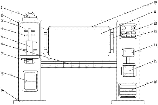
[0013] see figure 1 , the present invention provides a technical solution: a glue applicator for plywood production, comprising a colloid inlet 1, a workbench 6, a sponge 10 and a driving motor 15, the colloid inlet 1 is connected with the casing 2, and the colloid inlet 1 The rubber storage box 3 is installed below, and the inside of the rubber storage box 3 is fixed with a stirring rod 5, and a heating rod device is arranged inside the stirring rod 5, and a ...


PUM


Abstract

The invention discloses a glue applicator for plywood production, which comprises a glue inlet, a workbench, a sponge and a driving motor, the glue inlet is connected with a casing, and a stirring rod is fixed inside the glue storage box. A stirring blade is arranged on the stirring rod, a micro motor is installed inside the casing, an adjustment control box is fixed under the micro motor, a fixed base is installed on the casing, and a A rotating shaft, an operation panel is fixed on the outside of the casing, a gearbox is arranged inside the casing, and a circuit box is installed below the drive motor. The gluing machine used for plywood production is equipped with a sponge device wrapped on the gluing roller, and the glue is evenly applied. The glue storage box is equipped with a stirring and heating device, the glue is not easy to solidify, the production efficiency is high, the speed is fast, and it can be more comprehensive Carry out gluing operations to ensure that the board is evenly applied during the gluing process and has stronger adhesion.

Description

technical field [0001] The invention relates to the technical field of plywood production equipment, in particular to a gluing machine for plywood production. Background technique [0002] With the prosperity of the economy, the continuous improvement of people's living standards, the development of production technology is getting better and better, and people's use of time is becoming more and more demanding. In life, the requirements for mechanical equipment are getting higher and higher. Hope to pass The innovation of mechanical equipment to improve the working efficiency of mechanical equipment, reduce working hours, improve the efficiency of use, so that it can maximize its value. In the plywood industry, the same is true for gluing machines. With the rapid development of science and technology, gluing machines are in the There are a variety of styles on the market, but there are a series of problems in the glue applicators on the market now, such as no sponge device, ...

Claims


Application Information

Patent Timeline
Patent Type & Authority Applications(China)
IPC IPC(8): B05C1/08B05C11/10
CPCB05C1/0808B05C11/1042
Inventor 钟强
Owner FUJIAN PROVINCE WUPING COUNTY YUNHE WOOD IND CO LTD
Learn More