Air exhausting device for mechanical casting die

A technology of mechanical casting and exhaust device, applied in the field of mechanical casting, can solve the problems of casting defects of casting pores, poor exhaust effect, and small exhaust cross-sectional area, so as to achieve convenient and ingenious use, improve quality and efficiency, and enhance sealing. effect of effect

Inactive Publication Date: 2017-11-21
湖州永盛机械铸造有限公司
View PDF0 Cites 1 Cited by
  • Summary
  • Abstract
  • Description
  • Claims
  • Application Information

AI Technical Summary

Problems solved by technology

When the cavity-type reticulated exhaust plug is used for exhaust, after the surface of the mold is sprayed with paint during the production process, the gaps are often blocked, which is not easy to clean, and the exhaust effect becomes poor; the cavity of the exhaust plug is thin, and it is easy to stick to aluminum and damage it. It is not easy to replace after the exhaust; when the exhaust rod is used for exhaust, the exhaust cross-sectional area is small and the exhaust effect is poor, and in continuous pouring, once the exhaust gap is blocked, the exhaust device is not easy to disassemble, and the mold needs to be disassembled. In the casting production process, during the pouring process of high-temperature metal liquid, the gas generated by the high-temperature operation of the molding material and the air contained in the cavity space must be able to be excluded from the mold, otherwise, it will cause casting defects such as pores and oxidation. Thus causing certain troubles to the production enterprises

Method used


Image

  • Air exhausting device for mechanical casting die
  • Air exhausting device for mechanical casting die
  • Air exhausting device for mechanical casting die

Examples


Embodiment Construction

[0017] The following will clearly and completely describe the technical solutions in the embodiments of the present invention with reference to the accompanying drawings in the embodiments of the present invention. Obviously, the described embodiments are only some, not all, embodiments of the present invention.

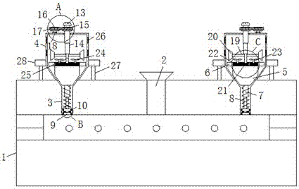
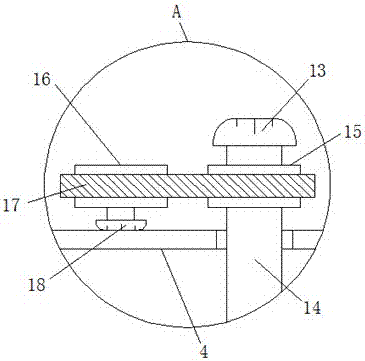
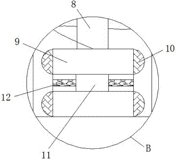
[0018] refer to Figure 1-4 , an exhaust device for a mechanical casting mold, comprising a mold 1 and an exhaust cover 4, the center of the upper end of the mold 1 is communicated with a pouring port 2, the two sides of the upper end of the mold 1 are symmetrically communicated with an exhaust channel 3, and the exhaust channel The upper end of 3 is provided with exhaust cover 4, and the two sides of the outer wall of exhaust cover 4 are symmetrically fixedly connected with fixed block 28, and the lower end of fixed block 28 is fixedly connected with support bar 27, and support bar 27 is fixed on the upper end of mold 1, row The air cover 4 is provided with a sealin...


PUM


Abstract

The invention discloses an exhaust device for a mechanical casting mold, which comprises a mold and an exhaust cover. The center of the upper end of the mold is communicated with a pouring port, and both sides of the upper end of the mold are symmetrically communicated with exhaust channels, and the exhaust The upper end of the channel is provided with an exhaust hood, the outer wall of the exhaust hood is fixedly connected with fixed blocks symmetrically on both sides, and the lower end of the fixed block is fixedly connected with a support rod, and the support rod is fixed on the upper end of the mold. A sealing plug is provided, and the upper end of the sealing plug is fixedly connected with a top cover. The end of the first telescopic rod extending into the exhaust passage is provided with a piston block, and the outer wall of the piston block is sleeved with two symmetrical sealing rings. A connecting shaft is provided at the end of the second telescopic rod extending inwardly through the top wall of the exhaust hood. The invention is simple in structure and easy to operate, can effectively dissipate heat and exhaust air during mechanical casting, ensures the integrity of the appearance of castings, and improves the quality and efficiency of products.

Description

technical field [0001] The invention relates to the technical field of mechanical casting, in particular to an exhaust device for a mechanical casting mold. Background technique [0002] At present, in the design of aluminum alloy casting metal molds, the molds generally use cavity-shaped vent plugs or exhaust rods for exhaust. When the cavity-type reticulated exhaust plug is used for exhaust, after the surface of the mold is sprayed with paint during the production process, the gaps are often blocked, which is not easy to clean, and the exhaust effect becomes poor; the cavity of the exhaust plug is thin, and it is easy to stick to aluminum and damage it. It is not easy to replace after the exhaust; when the exhaust rod is used for exhaust, the exhaust cross-sectional area is small, and the exhaust effect is poor, and in continuous pouring, once the exhaust gap is blocked, the exhaust device is not easy to disassemble, and the mold needs to be disassembled. In the casting p...

Claims


Application Information

Patent Timeline
Patent Type & Authority Applications(China)
IPC IPC(8): B22C9/06
CPCB22C9/067B22C9/065
Inventor 沈安康
Owner 湖州永盛机械铸造有限公司
Why Eureka
Try Eureka