

Wellhead drainage device with blade type closing valve
A drainage device and blade-type technology, which is applied to water supply devices, drainage structures, waterway systems, etc., can solve the problems of safety hazards, insufficient drainage of drainage pipes, etc., and achieve the effect of taking into account both environmental protection and water permeability
- Summary
- Abstract
- Description
- Claims
- Application Information
AI Technical Summary
Problems solved by technology
Method used
Image

Examples
Embodiment 1
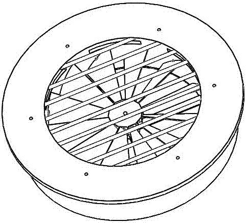
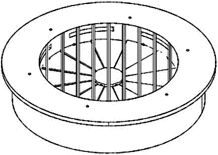
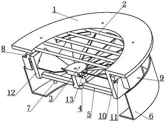
[0027] combined with Figure 1-3 As shown, a wellhead drainage device with a vane-type closed valve includes a fixedly connected upper casing and a lower casing 6, and a flat ring-shaped closed valve. The lower casing 6 is in the shape of a basin and the middle of the basin bottom Opening, the upper casing includes an inner cylinder 12 and an upper edge 1 for fixing on the ground, an annular cavity is formed between the inner cylinder 12 and the lower casing 6, and the outer wall of the inner cylinder 12 covers A push ring 8 is connected, and a plurality of plastic blocks 9 are fixed on the push ring 8; a cross mounting frame 5 is fixed on the inner wall of the inner cylinder 12, and a wheel hub fixing column 4 is fixedly arranged in the center of the cross mounting frame 5 , the top of the hub fixing column 4 is equipped with a hub 3, the centers of the hub 3, the inner tube 12, and the closed valve are on the same axis perpendicular to the plane of the hub, and the sides of ...
Embodiment 2
[0034] On the basis of Example 1, in conjunction with the attached image 3 As shown, the end of the mounting post at the narrow end of the blade 14 is sleeved with a return spring 13, one end of the return spring 13 is fixedly connected to the mounting post at the narrow end of the blade 14, and the other end is fixedly connected to the hub 3 An inner wall of the opening for receiving the mounting post.
[0035] When the drainage is finished, the water inlet on the inner cylinder 12 no longer has water inflow, and the water in the annular cavity is gradually discharged from the round hole at the bottom of the lower casing 6, and the water in the annular cavity The water level gradually decreases, and the buoyancy force on the plastic block 9 decreases. Under the action of gravity, the plastic block 9 and the push ring 8 fall, the push-pull rod 10 is pulled, and the rocker arm 11 is rotated. The return spring 13 twists the vane 14 back, and under the double action of the push...
PUM
 Abstract
Description
Claims
Application Information