Spiral electromagnetic sensor-based device for measuring bubble(s) in molten metal

An electromagnetic sensor and measuring device technology, applied in the direction of material magnetic variables, etc., can solve the problems of high cost, low measurement sensitivity, difficult to guarantee the accuracy of measurement, etc., and achieve the effect of good real-time performance.

Inactive Publication Date: 2017-11-21
QUFU NORMAL UNIV
View PDF5 Cites 2 Cited by
  • Summary
  • Abstract
  • Description
  • Claims
  • Application Information

AI Technical Summary

Problems solved by technology

For traditional contact measurement methods, on the one hand, it is necessary to make high-temperature and corrosion-resistant probes or electrodes with high cost; on the other hand, these contact sensors may change the distribution of the measured object field or the physical and chemical properties of the molten metal chemical nature, causing metal fluids to be contaminated
[0003] For non-contact measurement methods, ultrasonic testing and optical testing need to make special probes, which are expensive; in addition, the propagation speed of ultrasonic waves and light is affected by the physical properties of the medium, and the accuracy of measurement is difficult to guarantee
The electrical non-contact measurement method can realize low-cost and non-invasive measurement, but due to the "soft field" characteristic of the measurement system itself, the measurement sensitivity is low and the measurement is severely uneven
In the field close to the sensor, the measurement accuracy is high; in the center of the field, it is difficult to obtain a measurement value with a large amplitude

Method used


Image

  • Spiral electromagnetic sensor-based device for measuring bubble(s) in molten metal
  • Spiral electromagnetic sensor-based device for measuring bubble(s) in molten metal
  • Spiral electromagnetic sensor-based device for measuring bubble(s) in molten metal

Examples


Embodiment Construction

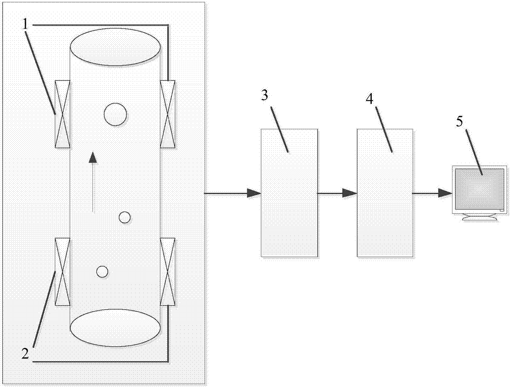
[0013] The structure of the device for measuring air bubbles in molten metal based on the helical electromagnetic sensor of the present invention will be further described in detail in conjunction with the accompanying drawings.
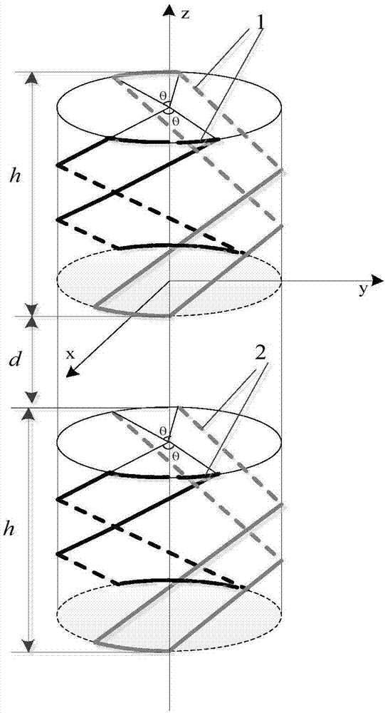
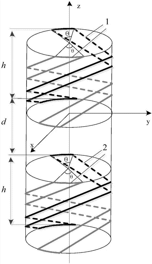
[0014] The design idea of ​​the bubble measuring device in molten metal based on the spiral electromagnetic sensor of the present invention is to adopt a spiral electromagnetic sensor group, which coaxially and parallelly surrounds two different sections on the surface of the measured pipeline in a spiral manner, with a certain axial distance. Keep a certain distance from the measured liquid to achieve non-contact and non-invasive measurement, while providing higher and more uniform sensitivity. Each sensor group includes an excitation coil and a receiving coil. Under certain other conditions, the helical electromagnetic sensor has three adjustable parameters: helix angle α, opening angle θ, and height h. The helix angle can be adjusted according to ...


PUM

PropertyMeasurementUnit
radiusaaaaaaaaaa

Abstract

The invention provides a spiral electromagnetic sensor-based device for measuring bubble(s) in molten metal. The device comprises an upstream electromagnetic sensor, a downstream electromagnetic sensor, a front end plate, a signal processing module and a host computer; and each of the upstream sensor and the downstream sensor includes an excitation coil and a detection coil, and the sensors are coaxially wound around the surface of a measured pipeline. The measuring device has the following steps: the measuring device utilizes the special spiral structure of the sensors to obtain a consistent and uniform sensitive field of a whole measured area; the device can detect a large-sized single bubble (with radius rb being more than r / 20) having a regular shape or a small bubble group in the molten metal with the caliber r being 0.1-1 m; the device and extract bubble parameter related quantitative information from a detection signal, and further derives the motion parameters of the bubble(s); and the device has a good real-time property, the working frequency can reach 10 MHz, and continuous acquisition of completely independent data points in the sampling process is guaranteed.

Description

technical field [0001] The invention belongs to the electromagnetic non-destructive testing technology, in particular to a bubble measuring device in molten metal based on a spiral electromagnetic sensor. Background technique [0002] The measurement of bubble parameters in molten metal has always been a difficult point in industrial measurement. For some industrial processes, such as the production of foamed aluminum, air bubbles in the metal melt are an important factor affecting product quality. In the production process of some metals or alloys, if the non-metallic inclusions (such as air bubbles) cannot be effectively controlled, it will not only affect the forming process of the product, but also greatly endanger the service performance of the metal material. Because the metal liquid has the characteristics of high temperature and opacity, and some liquids are corrosive to a certain extent, it is difficult to measure. For traditional contact measurement methods, on t...

Claims


Application Information

Patent Timeline
Patent Type & Authority Applications(China)
IPC IPC(8): G01N27/74
CPCG01N27/74
Inventor 赵倩尹武良曹佃国
Owner QUFU NORMAL UNIV
Why Eureka
Try Eureka