Powder flow pattern detection apparatus in spiral conveyer pipe and compression perception flow pattern identification method

A technology of spiral conveying tube and flow pattern detection, which is applied in the direction of measuring device, fluid dynamics test, machine/structural component test, etc. It can solve the problems of large measurement error, poor real-time performance, and limited number of output neurons.

Inactive Publication Date: 2014-03-19
JIANGSU UNIV
View PDF12 Cites 15 Cited by
  • Summary
  • Abstract
  • Description
  • Claims
  • Application Information

AI Technical Summary

Problems solved by technology

This type of method can measure the solid phase concentration of the two-phase flow, but due to the separation of the two fluids, the system is complicated, which may affect the continuity of the industrial process and limit its application range
The second category is based on ultrasonic technology, microwave technology, spectral technology, nuclear magnetic resonance technology, radiation technology, new tracer technology, related technology, capacitance method, process tomography and other new detection technologies, but many of these technologies are based on Phase flow measurement is still mostly in the experimental research stage or applied to special occasions, and there is still a long way to go before industrial production
However, due to the limited amount of information that can be obtained by ECT sensors, ECT image reconstruction is a process of solving an underdetermined ill-conditioned equation. Despite the efforts of domestic and foreign scholars for many years, the problem of ECT image reconstruction has not been well solved, and the obtained images are relatively poor. At the same time, due to the complex image reconstruction process, large amount of calculation, and poor real-time performance, the online application of ECT flow pattern recognition is limited.
[0007] Existing flow pattern identification algorithms, such as: In 2002, Peng Lihui and others introduced the principal component analysis method in the invention patent based on principal component analysis and neural network two-phase flow concentration measurement method (application number 02153486.1) after normalization Capacitance measurement value, avoiding the error caused by the traditional image reconstruction algorithm, but due to the limited number of output neurons, the imaging resolution is not high; The method and device (patent application number 200310108142.1) uses the back-projection algorithm to reconstruct the distribution image of the oil-gas two-phase flow medium, displays the flow pattern in the pipeline in real time, and uses fuzzy recognition for online automatic identification of the flow pattern. The discrimination accuracy is different; in 2010, Yang Daoye obtained the dielectric constant of the measured medium by adding a capacitive sampling sensor in the invention patent gas-solid two-phase flow online calibration capacitance tomography system and online calibration method (patent application number 201010146260.1), and the imaging system The hardware structure is complex and the measurement error is large
[0008] How to detect the powder flow pattern during the feeding process of the screw conveying pipeline has always been an industrial problem. Body movement is very complex
How to use the above technology to accurately and reliably detect the flow pattern of powder in the spiral conveying pipeline is a topic that needs further research. At present, there are no relevant reports on the detection of material flow pattern in the spiral conveying pipeline.

Method used


Image

  • Powder flow pattern detection apparatus in spiral conveyer pipe and compression perception flow pattern identification method
  • Powder flow pattern detection apparatus in spiral conveyer pipe and compression perception flow pattern identification method
  • Powder flow pattern detection apparatus in spiral conveyer pipe and compression perception flow pattern identification method

Examples


Embodiment Construction

[0068] The powder flow pattern detection device in the spiral conveying pipe and the compression sensing flow pattern identification method of the present invention will be described below with reference to the accompanying drawings and embodiments.

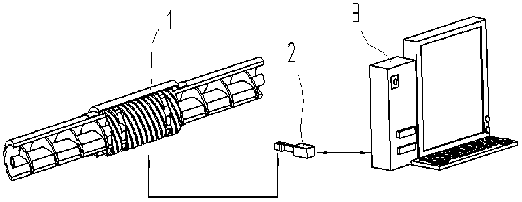
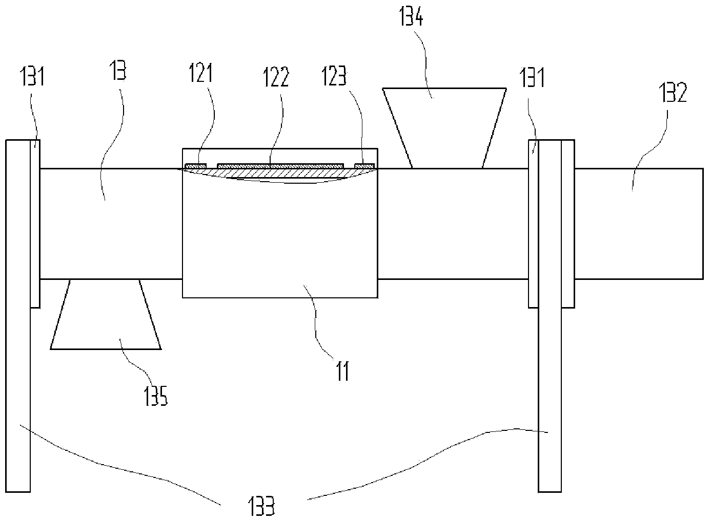
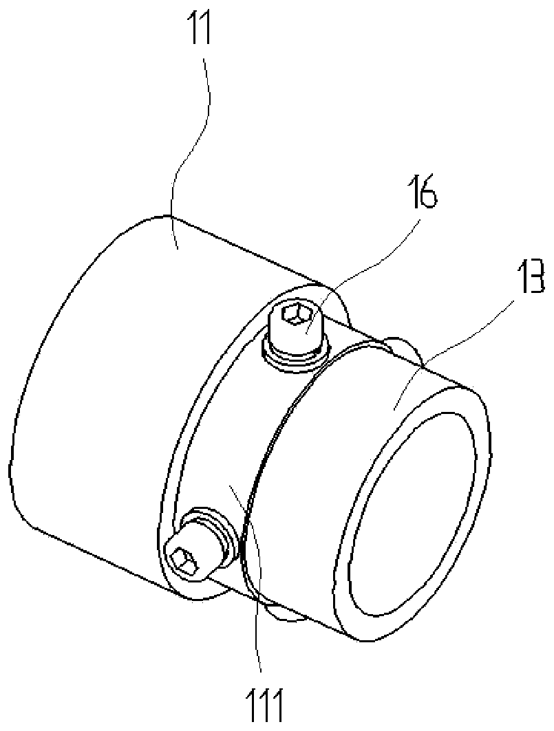
[0069] Such as figure 1 , figure 2 , image 3As shown, the powder flow pattern detection device in the screw conveying pipe of the present invention consists of a horizontal screw conveyor, a front-end shielding electrode array 121, a detection electrode array 122, an end shielding electrode array 123, a shielding cover 11, a signal acquisition and processing unit 2 and The upper computer consists of 3 components.

[0070] The positions and connections of each part are as follows: the horizontal screw conveyor includes a cylindrical insulating pipeline 13, a screw shaft 15 is installed inside the cylindrical insulating pipeline 13, and a screw blade 14 is wrapped around the screw shaft 15. Both ends of the cylindrical insulat...


PUM


Abstract

The invention discloses a powder flow pattern detection apparatus in a spiral conveyer pipe and a compression perception flow pattern identification method. The detection apparatus is formed by a detection sensor, a signal acquisition and processing unit and an upper computer. The detection sensor comprises a spiral front end shielding electrode array, a spiral detection electrode array, a spiral tail end shielding electrode array, a cylindrical insulation pipeline and a shielding cover. An algorithm based on a compression perception theory is used to carry out flow pattern identification so that a limitation of a traditional algorithm which needs to calculate a sensitivity matrix is overcome. By using the apparatus and the method of the invention, a uniform degree of a sensitive field of the detection sensor is greatly improved; the structure of a signal acquisition and processing circuit is simple; a calculated amount of a flow pattern identification algorithm is small; the flow pattern identification can be accurately and effectively performed; a problem of the flow pattern identification of the filled powder in the spiral conveyer pipe is solved; a good application prospect and an practical value are possessed.

Description

technical field [0001] The invention relates to an on-line detection device for powder in industrial production pipelines, specifically provides a powder flow pattern detection device in a spiral conveying pipe and a compression sensing flow pattern identification method, which belongs to the technical field of material conveying detection devices and can be applied to food, chemical industry, and agriculture and other industries. Background technique [0002] The spiral conveying pipeline has good controllability and stability for the transportation of powder and granular materials, and is widely used in the transportation, batching and packaging production process of industrial minerals, agricultural materials, chemicals, food processing raw materials and finished products. With the rapid development of these industries, the study of the flow mechanism of materials in the spiral conveying pipeline and the accurate detection of its various parameters are the basis for the r...

Claims


Application Information

Patent Timeline
Patent Type & Authority Applications(China)
IPC IPC(8): G01M10/00
Inventor 张西良吴琪孙祥王辉路欣徐云峰张世庆
Owner JIANGSU UNIV
Why Eureka
Try Eureka